Symmetrical parallel mechanism without singularities

A symmetrical and singular technology, applied in the field of symmetrical parallel mechanisms, can solve the problems of difficult mechanism trajectory planning, trajectory planning and control, etc., and achieve the effect of good motion characteristics, simple driving form and strong bearing capacity

Inactive Publication Date: 2016-06-01
XIAN UNIV OF TECH
View PDF7 Cites 7 Cited by
  • Summary
  • Abstract
  • Description
  • Claims
  • Application Information

AI Technical Summary

Problems solved by technology

However, the existing three-degree-of-freedom parallel mechanism has the problem of singular configuration, which makes the trajectory planning of the mechanism more difficult
Among the four-degree-of-freedom parallel mechanisms, there ar...

Method used


Image

  • Symmetrical parallel mechanism without singularities
  • Symmetrical parallel mechanism without singularities
  • Symmetrical parallel mechanism without singularities

Examples


Embodiment 1

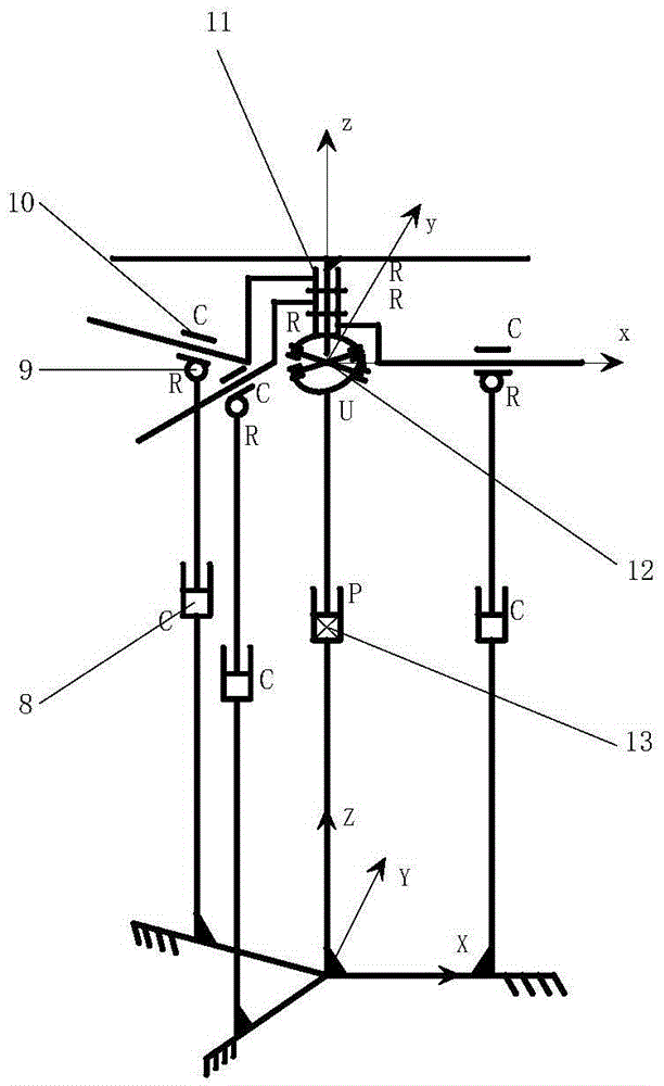
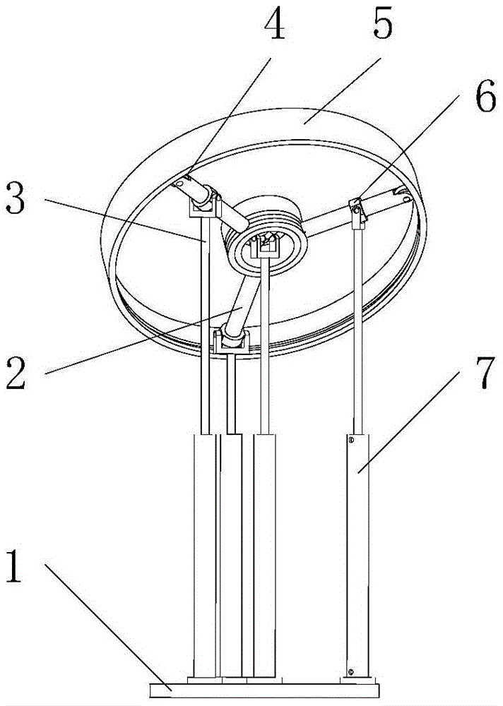
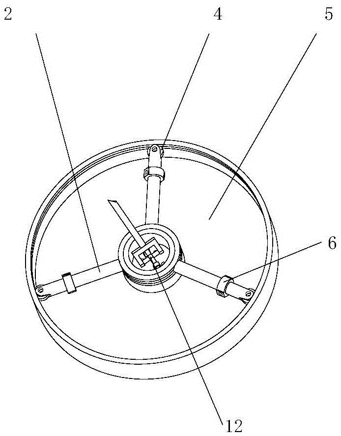
[0019] The present invention is a symmetrical parallel mechanism without singular configuration, such as figure 1 and figure 2 As shown, it includes the moving platform 5, the fixed platform 1 as the frame, and four motion branch chains connecting the moving platform and the fixed platform. And three identical motion branch chains, the three identical motion branch chains include the hydraulic cylinder 7 fixedly connected with the fixed platform 1, the three hydraulic cylinders 7 are respectively connected to the piston rod 3 through the cylinder pair A8, and the three piston rods 3 are respectively Connect with the ring member 6 through the rotating pair A9, such as image 3 As shown, the three annular members 6 are respectively connected to the sliding rod 2 through the cylindrical pair B10, one end of each sliding rod 2 is connected to the center of the moving platform 5 through the rotating pair B11, and the other end of the sliding rod 2 is connected to the roller 4 thr...

Embodiment 2

[0033] The present invention is a symmetrical parallel mechanism without singular configuration, such as figure 2 and Figure 4 As shown, it includes a moving platform 5, a fixed platform 1 as a frame, and four motion branch chains connecting the moving platform 5 and the fixed platform 1. Constraint chain and three identical motion branch chains, the three identical motion branch chains include hydraulic cylinder 7 fixedly connected with fixed platform 1, three hydraulic cylinders 7 and piston rod 3 through cylinder pair A8, and three piston rods 3 are respectively connected with the ring member 6 through the rotating pair A9, such as image 3As shown, the three annular members 6 are respectively connected to the sliding rod 2 through the cylindrical pair B10, one end of each sliding rod 2 is connected to the center of the moving platform 5 through the rotating pair B11, and the other end of the sliding rod 2 is connected to the roller 4 through the rotating pair, The roll...


PUM


Abstract

The invention discloses a symmetrical parallel mechanism without singularities. The symmetrical parallel mechanism without the singularities comprises a movable platform, a fixed platform used as a frame, and four kinematic chains connecting the movable platform and the fixed platform, wherein the four kinematic chains comprise a properly constrained chain connecting the central position of the movable platform and the central position of the fixed platform, and three identical kinematic branched chains; the three kinematic branched chains are symmetrically distributed about the centre of the properly constrained chain; the parallel mechanism has three degrees of freedom and four degrees of freedom respectively through addition or no addition of a revolute pair on the properly constrained chain; and the parallel mechanisms with the two degrees of freedom both have the characteristics of symmetrical structure and no singularities. The symmetrical parallel mechanism without the singularities, which is disclosed by the invention, can be applied to the fields of motion simulators, telescope secondary mirror support mechanisms, mechanical wrists, coordinate measuring machines, micro-operation robots, machine tool spindle heads and the like, and has a wide application prospect.

Description

technical field [0001] The invention belongs to the technical field of mechanical manufacturing and relates to a symmetrical parallel mechanism without singular configuration. Background technique [0002] Compared with the series mechanism, the parallel mechanism has the advantages of high rigidity, high load capacity, high precision and easy kinematic inverse solution, so it is widely used in the fields of industrial robots and machinery manufacturing. The parallel mechanism with less degrees of freedom (parallel mechanism with less than 6 degrees of freedom) has the characteristics of simple structure, low cost, and relatively simple kinematics solution. Among them, the three-degree-of-freedom parallel mechanism with two rotations and one movement is a very important one in parallel mechanisms. class configuration. Since HUNT proposed the 3-RPS parallel mechanism in 1983, the two-rotation-one-movement three-degree-of-freedom parallel mechanism has been used in many field...

Claims


Application Information

Patent Timeline
IPC IPC(8): B25J9/00
CPCB25J9/0072
Inventor 刘宏昭周少瑞
Owner XIAN UNIV OF TECH
Why Eureka
Try Eureka