Rail transit electric drive hydraulic brake control system

A hydraulic braking and rail transit technology, applied in the braking field of rail transit vehicles, can solve the problems of slow braking response and long braking force establishment time, and achieve precise control of braking force, light weight, and easy fault diagnosis. Effect

Active Publication Date: 2016-06-01
ZHUZHOU CSR TIMES ELECTRIC CO LTD
View PDF9 Cites 19 Cited by
  • Summary
  • Abstract
  • Description
  • Claims
  • Application Information

AI Technical Summary

Problems solved by technology

In the above-mentioned air-to-hydraulic braking system, the basic braking unit adopts a hydraulic method, and the brake cylinder is small in size and light in weight, b

Method used


Image

  • Rail transit electric drive hydraulic brake control system
  • Rail transit electric drive hydraulic brake control system
  • Rail transit electric drive hydraulic brake control system

Examples


Embodiment Construction

[0019] The present invention will be further described in detail below in conjunction with the accompanying drawings and specific embodiments.

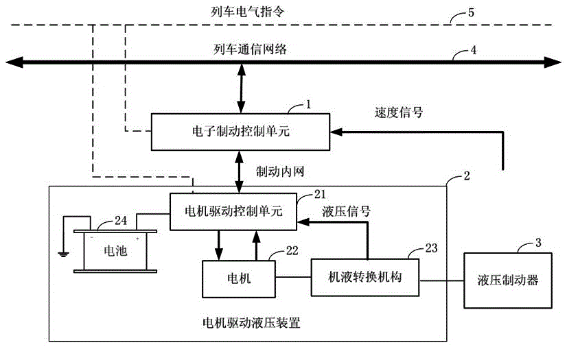
[0020] Such as figure 1 As shown, the rail transit electric drive hydraulic brake control system of the present invention includes an electronic brake control unit 1, a motor-driven hydraulic device 2 and a hydraulic brake 3, and the electronic brake control unit 1 receives the brake command through the train communication network 4 and For braking force distribution and control, the electronic brake control unit 1 performs data interaction with the motor-driven hydraulic device 2 through the brake internal network, and the motor-driven hydraulic device 2 converts the braking force request into a hydraulic signal, and the hydraulic signal drives the hydraulic brake 3 to complete action.

[0021] In this embodiment, the motor-driven hydraulic device 2 includes a motor-driven control unit 21, a motor 22, a mechanical-hydraulic conversi...


PUM


Abstract

The invention discloses a rail transit electric drive hydraulic brake control system.The rail transit electric drive hydraulic brake control system comprises an electronic brake control unit, a motor drive hydraulic device and a hydraulic brake.The electronic brake control unit receives brake instructions through a train communication network and allocates and controls braking force.The electronic brake control unit conducts data interaction with the motor drive hydraulic device through a brake intranet.The motor drive hydraulic device converts braking force requests into hydraulic signals which drive the hydraulic brake to finish actions.The rail transit electric drive hydraulic brake control system has the advantages of being simple and compact in structure, small in overall weight, high in pressure control precision, quick in control response and the like.

Description

technical field [0001] The invention mainly relates to the technical field of braking of rail transit vehicles, in particular to an electric drive hydraulic braking control system suitable for rail transit vehicles. Background technique [0002] At present, in the braking system of rail transit vehicles, there are mainly three types: full hydraulic braking system, full pneumatic braking system (air braking) and air-to-hydraulic braking system. [0003] In the braking system that adopts the full hydraulic braking method, the hydraulic pump provides high-pressure oil and stores it in the energy storage cylinder, and then controls the pressure of the hydraulic oil through various solenoid valves according to the control instructions of the electronic brake control unit. The adjusted brake oil pressure enters the basic brake unit to push the brake shoe to press the wheel to generate braking force. The hydraulic pressure of the full hydraulic braking system is relatively high. U...

Claims


Application Information

Patent Timeline
IPC IPC(8): B60T8/17B60T13/66
CPCB60T8/1705B60T13/66B60T2201/02
Inventor 段炼刘海涛钱华夏帅谢永清戴博文
Owner ZHUZHOU CSR TIMES ELECTRIC CO LTD
Why Eureka
Try Eureka