
Reverse osmosis water purification machine system for automatically adjusting recovery rate and control method thereof

A technology of automatic adjustment and recovery rate, applied in water treatment parameter control, permeation/dialysis water/sewage treatment, chemical instruments and methods, etc., can solve problems such as no water saving method, reduced service life, and pollutant blockage, etc., to achieve The effects of avoiding waste of water resources, improving technical level, and saving flushing water

Inactive Publication Date: 2016-06-01
SHANGHAI OZNER WATER PURIFICATION SCI & TECH DEV
View PDF3 Cites 10 Cited by
  • Summary
  • Abstract
  • Description
  • Claims
  • Application Information

AI Technical Summary

Problems solved by technology

[0005] However, the reuse of concentrated water will bring another problem, because the precision of RO membrane material is nanometer level, it is easy to cause clogging of pollutants, especially in areas with poor water quality, RO membrane is used in concentrated water reuse It is more likely to cause clogging, greatly reduce the service life, and cause unnecessary waste. In the process of flushing the RO membrane, a large amount of flushing water is required. At present, there is no effective water-saving method
[0006] At the same time, blindly pursuing a water-saving process with a high recovery rate will cause the salinity of the effluent to be higher than the customer's acceptable range in areas with high salinity, and even lower than the 90% desalination rate standard stipulated by the state for reverse osmosis devices, resulting in People's misconceptions about product quality

Method used


Image

  • Reverse osmosis water purification machine system for automatically adjusting recovery rate and control method thereof
  • Reverse osmosis water purification machine system for automatically adjusting recovery rate and control method thereof

Examples


Embodiment Construction

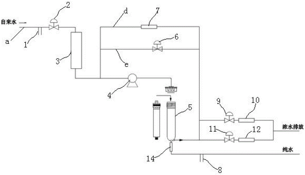
[0027] The present invention will be described in further detail below in conjunction with the accompanying drawings and embodiments. The embodiments are not intended to limit the scope of protection of the invention. Obviously, those skilled in the art can obtain other embodiments without having to pay creative work. Belong to the protection scope of the present invention.

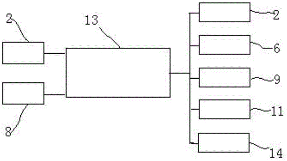
[0028] combine figure 1 As shown, a reverse osmosis pure water machine system that automatically adjusts the recovery rate, which includes the first TDS probe 1 installed on the pipeline a, the water inlet solenoid valve 2, the pre-filter system 3, and the booster pump 4 , RO membrane 5, the external water source of the pipeline is tap water. The pipeline connected to the concentrated water outlet of the RO membrane includes two parallel pipelines b, c, in which a first solenoid valve 11 and a first waste water ratio 12 are sequentially installed on one pipeline, and a second electromagnetic valve is seq...


PUM


Abstract

The invention relates to a reverse osmosis water purification machine system for automatically adjusting the recovery rate. The reverse osmosis water purification machine system comprises a first TDS probe, a water inlet electromagnetic valve, a front-arranged filtering system, a booster pump and an RO membrane which are sequentially installed on a pipeline. Pipelines connected with a thick water outlet of the RO membrane comprise two parallel pipelines. The two pipelines are each provided with an electromagnetic valve and a waste water meter. A check valve and a second TDS probe are installed on a pipeline of a pure water outlet of the RO membrane. A third waste water meter is connected with between the thick water outlet of the RO membrane and a water inlet of the booster pump in parallel. A flushing electromagnetic valve is installed between the thick water outlet of the RO membrane and the water inlet of the booster pump in parallel. The two TDS probes, the flushing electromagnetic valve and an electromagnetic valve system are connected with a control system. The invention further discloses a control method of the reverse osmosis water purification machine system. The system can adjust the recovery rate automatically according to the detection result, save water for flushing the RO membrane, avoid unnecessary waste resource waste, and greatly improve the technological level of the existing industry.

Description

technical field [0001] The invention relates to a reverse osmosis pure water machine system, in particular to a reverse osmosis pure water machine system which automatically adjusts the recovery rate according to the water quality. The utility model belongs to the technical field of a reverse osmosis pure water machine. Background technique [0002] For reverse osmosis water purifiers, the national standard stipulates that the recovery rate should not be less than 30%, that is, the purified water and concentrated water should not be less than 1:2.3, that is to say, for every 1 cup of purified water produced, 2.3 cups of concentrated water need to be drained . And this ratio is estimated based on the national inventory of reverse osmosis water purifiers, and the amount of water wasted every day is staggeringly terrifying. According to market data, the number of reverse osmosis water purifiers in use across the country is calculated as 15 million household machines and 5 mil...

Claims


Application Information

Patent Timeline
Patent Type & Authority Applications(China)
IPC IPC(8): C02F1/44
CPCC02F1/441C02F2209/10C02F2303/16
Inventor 肖述
Owner SHANGHAI OZNER WATER PURIFICATION SCI & TECH DEV
Learn More