
Connection joint and connection structure of light-weight wallboard frame

A technology of lightweight wall panels and connecting joints, used in building components, building structures, buildings, etc., can solve the problems of frame joints that cannot be directly connected, inconvenient for storage and transportation, affecting assembly speed, etc., and achieves low labor intensity for workers. , saving logistics costs, in addition to the effect of low production costs

Active Publication Date: 2017-12-15
YUNNAN BANZHU TECH CO LTD
View PDF6 Cites 0 Cited by
  • Summary
  • Abstract
  • Description
  • Claims
  • Application Information

AI Technical Summary

Problems solved by technology

[0002] At present, the frames of light-weight wall panels are generally cut at beveled angles and then welded to connect, but on-site welding is required, which affects the assembly speed. If it is welded into a frame first, it is inconvenient to store and transport; and some light-weight wall panels In order to facilitate mutual positioning and connection, grooves or convex grooves are provided on the keel of the frame, and the groove or convex groove extends along the length direction of the top surface of the keel. At the same time, because there are concave and convex grooves (the adjacent keels of the rectangular frame are generally grooves and convex grooves), they cannot be aligned, so that the frame joints cannot be directly connected, and the ends of the keels must be reshaped and flattened before connecting. Manufacturing troubles, low production efficiency and high cost

Method used


Image

  • Connection joint and connection structure of light-weight wallboard frame
  • Connection joint and connection structure of light-weight wallboard frame
  • Connection joint and connection structure of light-weight wallboard frame

Examples


Embodiment Construction

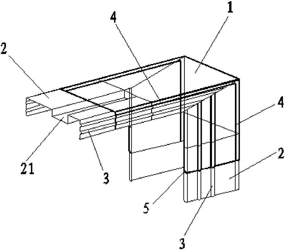
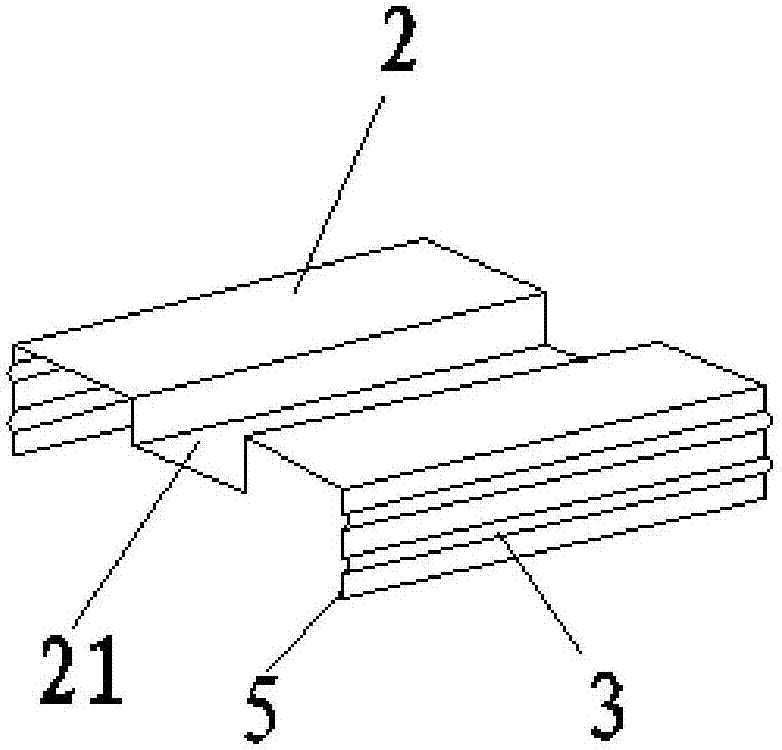
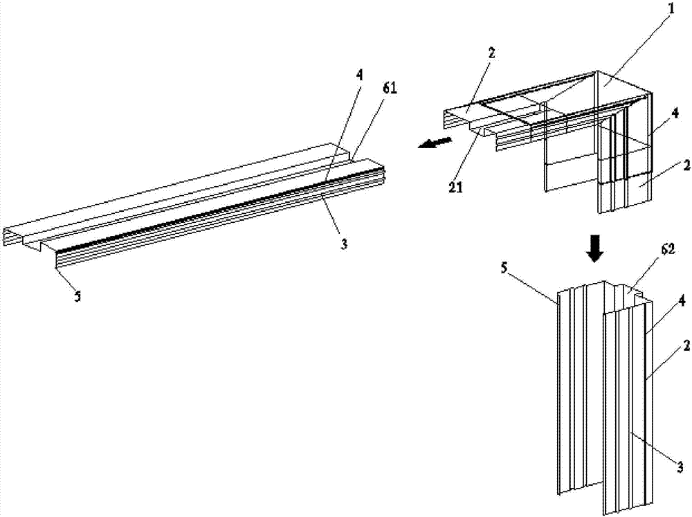
[0025] Such as figure 1 , figure 2 and image 3 As shown, a connection joint of a lightweight wallboard frame includes an outer wrapping angle 1 and a plug joint 2. The outer wrapping angle 1 is a groove-shaped profile including a top surface and two sides. The outer wrapping angle 1 in this embodiment is a right angle Shape, the plug connector 2 and the outer corner 1 are fixed on both ends of the outer corner 1, a part of the plug connector 2 is located in the notch of the outer corner 1, and the other part protrudes from the outer corner 1. The plug joint 2 is a groove-shaped profile including the top surface and two sides. The slots of the plug joint 2 and the outer corner 1 are in the same direction. Groove 21, said protruding line or groove 21 is provided at least on the top surface section of the plug joint 2 protruding from the outer corner 1, and the two sides of the plug joint 2 are provided with reinforcing ribs 3. The plug connector 2 is set in a groove shape w...


PUM


Abstract

The invention provides a light connection joint and connection structure for wallboard side frames. The connection joint comprises an outer wrapping corner and connecting plugs, the outer wrapping corner comprises a groove-shaped profile on the top face and groove-shaped profiles on the two side faces, the connecting plugs are fixed to the two ends of the outer wrapping corner in a mode that the connecting plugs are in fit with the outer wrapping corner, one part of each connecting plug is located in a corresponding notch of the outer wrapping corner, and the other part of each connecting plug extends out of the outer wrapping corner; the connecting plugs are provided with protruding strips or grooves in fit with concave-convex butt-joint portions of the top face of a keel. By means of the light connection joint and connection structure, connection at the side frame joint position can be simple and convenient, labor intensity of workers is low, production efficiency is high, production cost is low, the assembled type side frames are adopted, mechanized, automated and standardized machining and production are achieved easily, and quality standards are more unified.

Description

technical field [0001] The invention relates to the field of lightweight wall panel construction, in particular to a connection joint and a connection structure of a frame of a lightweight wall panel. Background technique [0002] At present, the frames of lightweight wall panels are usually cut at beveled angles and then welded to connect, but on-site welding is required, which affects the assembly speed. If it is welded into a frame first, it is inconvenient to store and transport; and some lightweight wall panels In order to facilitate mutual positioning and connection, grooves or convex grooves are provided on the keel of the frame, and the groove or convex groove extends along the length direction of the top surface of the keel. At the same time, because there are concave and convex grooves (the adjacent keels of the rectangular frame are generally grooves and convex grooves), they cannot be aligned, so that the frame joints cannot be directly connected, and the ends of...

Claims


Application Information

Patent Timeline
Patent Type & Authority Patents(China)
IPC IPC(8): E04C2/38
CPCE04C2/38E04C2/384
Inventor 唐进丰唐元元唐方方
Owner YUNNAN BANZHU TECH CO LTD
Learn More