Wind farm and wind power generation system

A technology of wind farms and wind turbines, applied to wind power generation, wind engines, wind engines consistent with the wind direction, etc., which can solve problems such as difficulty in improving efficiency, difficulty in coping with sudden changes in wind speed and direction, and difficulties in power generation output

Inactive Publication Date: 2016-06-01
KK TOSHIBA
View PDF5 Cites 2 Cited by
  • Summary
  • Abstract
  • Description
  • Claims
  • Application Information

AI Technical Summary

Problems solved by technology

Does not readily respond adequately to sudden changes in wind speed and direction by adjusting yaw or pitch angles
Therefore, in this wind power generation system, it is difficult to maintain the power generation output stably, so it is sometimes not easy to improve the efficiency

Method used


Image

  • Wind farm and wind power generation system
  • Wind farm and wind power generation system
  • Wind farm and wind power generation system

Examples


no. 1 example

[0043] [A] Structure etc.

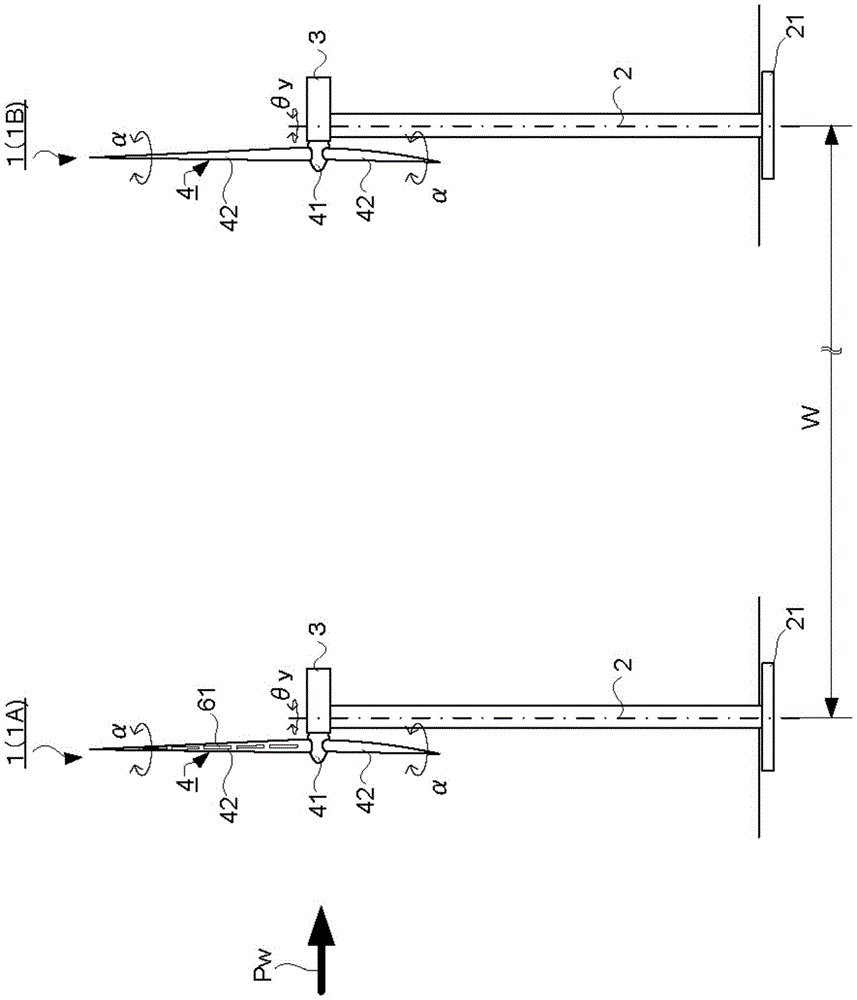
[0044] figure 1 It is a view showing a state in which a plurality of wind turbines 1 are arranged in the wind farm according to the first embodiment. figure 1 It is a side view and shows some of the plurality of wind turbines 1.

[0045] figure 1 Two wind turbines 1 arranged next to each other in a wind direction having an annual frequency higher than a predetermined value in the wind direction of wind blowing in an installation area in which a plurality of wind turbines are installed in a wind farm are shown. Here, two wind turbines 1 along the main wind direction Pw (wind direction with the highest frequency throughout the year) are shown as an example. Therefore, if the wind blowing from north to south is the main wind and the main wind direction Pw is north to south, then it is shown in figure 1 The two wind turbines 1 in this are wind turbines arranged in this north-south direction, the left wind turbine 1A (first wind turbine) is located on the...

no. 2 example

[0075] [A] Structure etc.

[0076] Figure 5 It is a diagram schematically showing a wind turbine equipped with an air flow generating device in a wind power generation system according to the second embodiment. Figure 5 Is similar to Picture 8 Perspective view.

[0077] Such as Figure 5 As shown, in the wind power generation system of this embodiment, the manner in which the air flow generating device 61 is installed in the wind turbine 1 is related to the related technology (refer to Picture 8 ) Is different.

[0078] This embodiment and the aforementioned related technology (refer to Picture 8 ) Is the same, except for the above points and related points. Therefore, in this embodiment, the description of the same parts as in the aforementioned related art will be omitted when appropriate.

[0079] In this embodiment, such as Figure 5 As shown, and the aforementioned related technology (refer to Picture 8 ) Is different, the air flow generating device 61 is not installed in all t...


PUM


Abstract

A wind farm of an embodiment includes a wind turbine and an airflow generation device, the wind turbine being installed in plurality in a predetermined installation region. The wind turbines each have a blade attached to a rotor. The airflow generation device includes a first electrode and a second electrode which are provided on a substrate formed of an insulating material. Here, the plural wind turbines include: a first wind turbine located on an upstream side and a second wind turbine located on a more downstream side than the first wind turbine, in a wind direction with a higher yearly frequency than a predetermined value, out of wind directions of wind blowing in the installation region. The airflow generation device is installed on the blade provided in the first wind turbine out of the plural wind turbines.

Description

Technical field [0001] The embodiments described herein generally involve wind farms and wind power generation systems. Background technique [0002] A wind power generation system has a wind turbine in which blades (wind turbine blades) are attached to a rotor, and the wind turbine generates electricity by rotating the rotor using wind energy, which is a renewable energy source. [0003] In this wind power generation system, a divided air flow is sometimes formed on the surface of the blade to change the amount of power generation. For example, when the wind speed or direction changes suddenly, the speed triangle around the blades deviates greatly from the rated point, so the divided airflow is formed in a wide range. It is not easy to adequately respond to sudden changes in wind speed and direction by adjusting the yaw angle or pitch angle. Therefore, in this wind power generation system, it is difficult to stably maintain the power generation output, and therefore it is someti...

Claims


Application Information

Patent Timeline
Patent Type & Authority Applications(China)
IPC IPC(8): F03D1/06F03D80/00
CPCF03D1/06F03D7/022F03D7/048Y02E10/72F03D7/0276F03D1/0675
Inventor 松田寿田中元史大迫俊树山崎显一浅山雅弘志村尚彦猪亦麻子
Owner KK TOSHIBA
Why Eureka
Try Eureka