Light source brightness detecting system and method

A technology of light source brightness and detection system, applied in photometry, optical radiation measurement, measurement device, etc., can solve problems such as blurry screen, dead pixels, and too dark display in a certain area, and achieve the effect of rapid detection

Inactive Publication Date: 2016-06-01
FU TAI HUA IND SHENZHEN +1
View PDF7 Cites 6 Cited by
  • Summary
  • Abstract
  • Description
  • Claims
  • Application Information

AI Technical Summary

Problems solved by technology

However, the equipment using the above-mentioned electronic light source will have problems such as blurred screen, dead pixels, uneven brightness distribution, etc.
The existing light source detection system can only simply detect bad pixels (that is, a certain light-emitting diode of the light source dot matrix is ​​on or off), and cannot well reflect the brightness distribution of the light source dot matrix, for example, a certain area Problems such as partial brightness or a certain area is too dark

Method used


Image

  • Light source brightness detecting system and method
  • Light source brightness detecting system and method
  • Light source brightness detecting system and method

Examples


Embodiment Construction

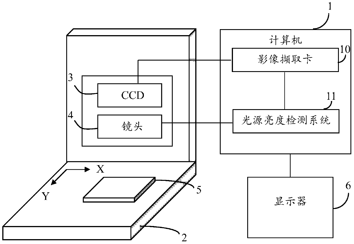
[0018] Refer to figure 1 Shown is a hardware architecture diagram of a preferred embodiment of the light source brightness detection system of the present invention. The light source brightness detection system is applied to the computer 1. The computer 1 is connected with an image measuring machine 2 on which a light emitting device 5 is placed. Wherein, the Z-axis of the image measuring machine 2 is equipped with a Charged Coupled Device (CCD) 3 for collecting continuous images, the CCD 3 is connected with a lens 4 through a cylindrical structure, and the CCD 3 is matched with the lens 4 The light emitting device 5 can be imaged. The light emitting device 5 can be installed on the working platform of the image measuring machine 2, for example, embedded in the working platform to form a seamless plane with the working platform, or it can be placed protrudingly on the working platform. The light-emitting device 5 is a dot-matrix light-emitting body, that is, composed of a plu...


PUM


Abstract

A light source brightness detecting method is provided. The method comprises the steps of: setting detection parameters; shooting an image of a light emitting device, and analyzing the shot image of the light emitting device so as to obtain a pixel brightness value of each light point in the light emitting device; and according to the detection parameters and the pixel brightness value of each light point, detecting each light point in the light emitting device so as to obtain the light emitting information of the light emitting device. The invention further provides a light source brightness detecting system. By adopting the light source brightness detecting system and method, the brightness of the light emitting device can be measured.

Description

Technical field [0001] The invention relates to an image measurement system and method, in particular to a light source brightness detection system and method. Background technique [0002] Display screens or lighting devices that use various electronic light sources (such as light emitting diodes, Light Emitting Diode, LED) to emit light are becoming more and more popular. However, the devices using the above electronic light sources may have problems such as blurring, dead pixels, and uneven brightness distribution. The existing light source detection system can only simply detect dead pixels (that is, a certain light-emitting diode of the light source dot matrix is ​​bright or not bright), and cannot well reflect the brightness distribution of the light source dot matrix, for example, a certain area Problems such as bright or dark display of a certain area. Summary of the invention [0003] In view of the above, it is necessary to provide a light source brightness detection s...

Claims


Application Information

Patent Timeline
Patent Type & Authority Applications(China)
IPC IPC(8): G01J1/42
CPCG01J2001/4252G01J1/4228G01J1/0228G01J1/44
Inventor 张旨光吴新元杨路
Owner FU TAI HUA IND SHENZHEN
Why Eureka
Try Eureka