Metallographic section sample preparation mold and method for preparing metallographic section sample

A technology for metallographic sectioning and sample preparation molds, which is applied in the preparation, sampling, and measuring devices of test samples, which can solve the problems of artificial randomness in sample preparation numbers and the influence of time on test result reappearance, so as to facilitate review , Improve sample preparation efficiency and avoid confusion

Inactive Publication Date: 2018-07-20
UNIV OF ELECTRONICS SCI & TECH OF CHINA
View PDF15 Cites 0 Cited by
  • Summary
  • Abstract
  • Description
  • Claims
  • Application Information

AI Technical Summary

Problems solved by technology

This method completes the sealing and marking of the sample in one step, which can realize the permanent unified marking of the metallographic section, and can solve the problems that the existing sample numbering is artificially random, and the reappearance of the test results is affected by time, etc.

Method used


Image

  • Metallographic section sample preparation mold and method for preparing metallographic section sample
  • Metallographic section sample preparation mold and method for preparing metallographic section sample
  • Metallographic section sample preparation mold and method for preparing metallographic section sample

Examples


Embodiment 1

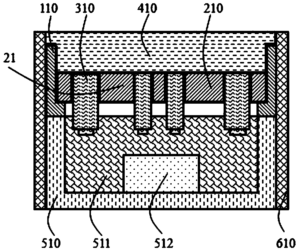
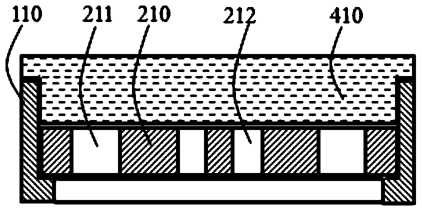
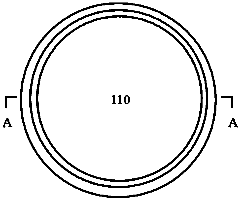
[0047] A metallographic section sample preparation mold, comprising: a rigid overcoat 610, a section glue-filling inner sleeve 510 inside the rigid overcoat 10 and a slice marking inner sleeve 21; the slice marking inner sleeve 21 is located above the section glue-filling inner sleeve 510, comprising The rigid shell 110, the elastic inner pad 210 inside the rigid shell 110 for placing movable type; the elastic inner pad is provided with a positioning hole for fixing the movable type, and the positioning hole is a through hole running through the bottom of the elastic inner pad. The slice marking inner sleeve 510 is used for injecting resin 511 after placing the sample 512, and the slice marking inner sleeve 21 and movable type 310 together form a slice marking assembly.

[0048] The inner diameter of the rigid overcoat is the same as the outer diameter of the slice glue-filled inner sleeve, and the size of the outer wall of the slice marking inner sleeve is consistent with the ...

Embodiment 2

[0060] This embodiment is basically the same as Embodiment 1, the difference is that the date movable type 211 of the elastic inner pad in this embodiment is distributed in a straight line in the center of the elastic inner pad, and the date of the sample main label movable type 212 and sub-label movable type 213 is located in the middle of the elastic inner pad On both sides of the upper and lower sides of the movable type 211, the movable type of the main label and the movable type of the secondary label can flexibly choose one or a combination of numbers and letters.

[0061] Such as Figure 16-18 As shown, the movable type used in this embodiment is suspended on the inner pad of the elastic body through the card position 62 at the top.

Embodiment 3

[0063] This embodiment is basically the same as Embodiment 1, except that the positioning hole is a blind hole extending upward from the bottom of the elastic inner pad. Such as Figure 19 As shown, the blind holes are used to fix the type while keeping the type vertical. Therefore, the slice marker inner sleeve does not need a top cover in this embodiment.


PUM

PropertyMeasurementUnit
thicknessaaaaaaaaaa

Abstract

The invention provides a metallographic section sample preparation mold and a method for preparing a metallographic section sample by using the mold. The mold includes: a rigid outer casing, a section glue filling inner casing and a section marking inner casing; the section marking inner casing includes a rigid shell, The elastic inner pad inside the rigid body shell is used to place movable type; the elastic inner pad is provided with a positioning hole, and the inner sleeve of the slice is used to place the sample and then inject resin, and the inner sleeve of the slice mark and the movable type together form a slice mark assembly; preparation The method includes the steps of: sampling, glue filling, placing a slice marking assembly, post-processing and detection; the invention realizes the combination of sample making and marking process, improves sample preparation efficiency and reduces sample preparation cost; uses movable type to mark slices , can flexibly mark the sample production date and sample label, form a unified and standardized experimental sample marking method, avoid confusion between multiple metallographic sections, and permanent marking is conducive to the observation record of the later section and the review of the test results.

Description

technical field [0001] The invention belongs to the technical field of printed circuit board production, in particular to a metallographic section sample preparation mold and a method for preparing printed circuit board metallographic sections using the mold. Background technique [0002] Printed circuit boards are one of the key components in electronic assemblies. With the rapid development of electronic science and technology, the application fields of electronic products are expanding, which has improved the status of printed circuit board manufacturing. In view of the fact that the reliability of printed circuit boards directly affects the quality of electronic products, improving the quality of printed circuit boards has become a hot spot in the industry. The intelligent and portable development direction of electronic products has promoted the progress of printed circuit board manufacturing technology in the direction of multilayer and integration, making the printed ...

Claims


Application Information

Patent Timeline
Patent Type & Authority Patents(China)
IPC IPC(8): G01N1/28
CPCG01N1/286G01N2001/2873
Inventor 何雪梅何为王守绪陈苑明周国云陈国琴申桃
Owner UNIV OF ELECTRONICS SCI & TECH OF CHINA
Why Eureka
Try Eureka