Light emitter, wavelength alignment method, and passive optical network system

An optical transmitter, a technology for emitting light, applied in the field of optical fiber communication, can solve the problem of serious chirp phenomenon, DML can not adapt to the transmitter and so on

Active Publication Date: 2016-06-01
锐智信息科技(滨州)有限公司
View PDF5 Cites 15 Cited by
  • Summary
  • Abstract
  • Description
  • Claims
  • Application Information

AI Technical Summary

Problems solved by technology

[0007] In view of this, the embodiment of the present invention provides an optical transmitter, a wavelength alignment method and a passive optical network system to overcome the problem that DML cannot adapt to 10GPON and higher rate PON system transmitters in the prior art, thus Problems that cause severe chirp phenomena

Method used


Image

  • Light emitter, wavelength alignment method, and passive optical network system
  • Light emitter, wavelength alignment method, and passive optical network system
  • Light emitter, wavelength alignment method, and passive optical network system

Examples


Embodiment 1

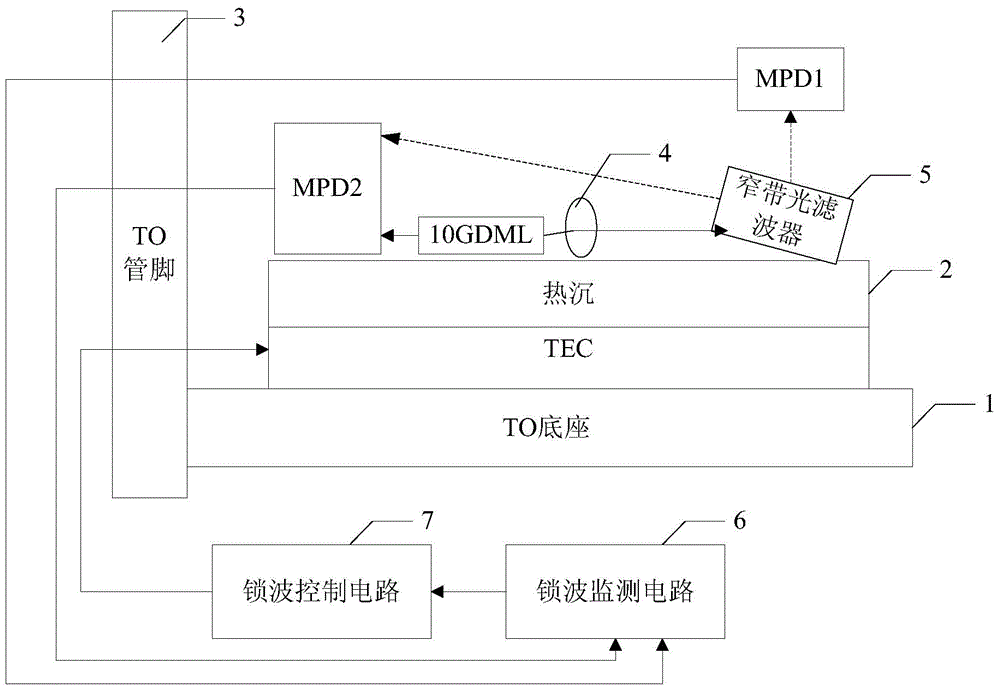
[0119] Such as figure 1 As shown, it is an optical transmitter disclosed in the embodiment of the present invention, which mainly includes:

[0120] TO base 1, TEC and heat sink 2 connected horizontally from bottom to top;

[0121]a TO pin 3 connected to one end of the TO base 1 on one side;

[0122] The second MPD ( figure 1 shown as MPD2), 10GDML, collimator lens 4 and narrow-band optical filter 5, wherein, the MPD2 and the collimator lens 4 are located on both sides of the 10GDML, and the narrow-band optical filter 5 is located on the collimator The other side of the collimating lens 4, and the side facing the collimating lens 4 is connected to the heat sink 2 at a preset inclination angle;

[0123] The first MPD ( figure 1 shown as MPD1 in );

[0124] A wave-locking monitoring circuit 6 connected to the TO pin 3 arranged on one side of the TO base 1, and a wave-locking control circuit 7 connected to the wave-locking monitoring circuit 6;

[0125] Wherein, the forward...

Embodiment 2

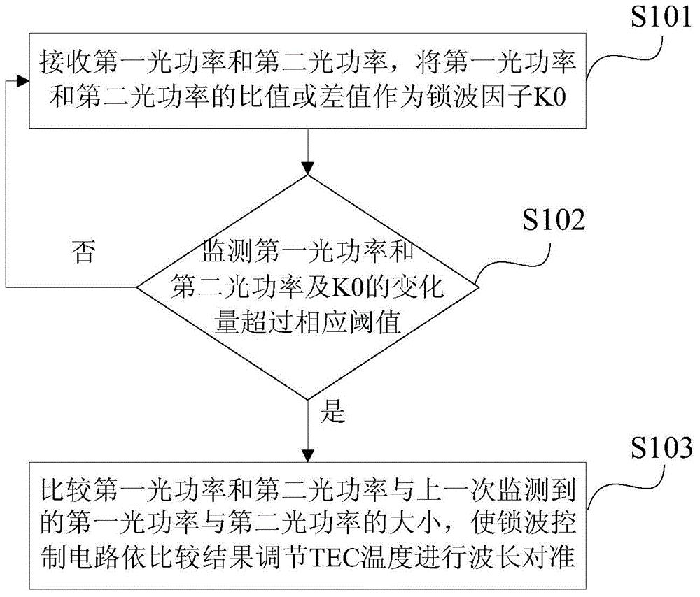
[0139] On the basis of the optical transmitter disclosed in the first embodiment of the present invention, based on the optical transmitter, the embodiment of the present invention also discloses a wavelength alignment method correspondingly. The method is based on the aforementioned figure 1 The structure diagram of the optical transmitter shown in figure 2 As shown, it mainly includes the following steps:

[0140] Step S101, the wave-locking monitoring circuit receives the first optical power of the forward transmitted light monitored by the first MPD through the TO pin and the second optical power of the complementary backward emitted light and retroreflected light monitored by the second MPD, and the The ratio or difference between the first optical power and the second optical power is used as the wave locking factor K0;

[0141] During the execution of step S101, based on the attached figure 1 In the disclosed optical transmitter, the forward transmitted light monitor...

Embodiment 3

[0150]On the basis of the optical transmitter disclosed in the first embodiment of the present invention and the wavelength alignment method disclosed in the second embodiment of the present invention, in step S101, the wave-locking monitoring circuit receives the first MPD through the TO pin to monitor the forward transmitted light Before the second optical power of the first optical power and the second MPD monitoring the second optical power after the back-emitted light and the back-reflected light are complementary, the following steps are also included:

[0151] In step S100, the wave-locking monitoring circuit reads the TEC temperature at the standard operating point, the first standard optical power M1 of the first MPD, and the second standard optical power M2 of the second MPD, and in the preset wavelength effective region with t* M1+M2 calculates the average optical power Pa, and uses Pa as the input of the automatic optical power control loop, wherein the input end of...


PUM


Abstract

The embodiment of the invention discloses a light emitter, a wavelength alignment method, and a passive optical network system. The light emitter achieves the monitoring of optical power in a TO through the arrangement of 10GDML, MPD1, MPD2, a collimating lens and a narrow band optical filter, carries out the monitoring of the optical power through the MPD1 and MPD 2, and outputting the monitored optical power to be outputted to a wave locking monitoring circuit through a TO pin. The change amount of the optical power monitored by the wave locking monitoring circuit and the change amount of a wave locking factor K0 are respectively compared with corresponding threshold values, and a comparison result is transmitted to the wave locking monitoring circuit, thereby enabling the wave locking monitoring circuit to adjust the TEC temperature for wavelength alignment through the TO pin according to the comparison result. The above wavelength monitoring loop is used for the wave locking control of the 10GDML wavelength and a filter, achieves low cost and power consumption, and reduces a high modulation rate of chirps.

Description

technical field [0001] The invention relates to the technical field of optical fiber communication, and more specifically relates to an optical transmitter, a wavelength alignment method and a passive optical network system. Background technique [0002] Based on the continuous increase of users' demand for bandwidth, as a new generation of broadband access network optical fiber access network, its highly competitive PON (Passive Optical Network, Passive Optical Network) system has become the main object used by users. Among them, the PON system usually includes an OLT (OpticalLineTerminal, optical line terminal) located in the central office, an ODN (OpticalDistributionNetwork, optical distribution network) for branching / coupling or multiplexing / demultiplexing, and several ONUs (OpticalNetworkUnit, optical network unit). [0003] However, with the continuous and rapid development of various broadband services such as video conferencing, 3D TV, mobile backhaul, interactive ...

Claims


Application Information

Patent Timeline
Patent Type & Authority Applications(China)
IPC IPC(8): H04B10/572
CPCH01S5/02212H01S5/02415H01S5/02438H01S5/0687H04B10/572H01S5/00
Inventor 廖振兴汪灵杰周敏黄晶
Owner 锐智信息科技(滨州)有限公司
Why Eureka
Try Eureka