
SR information acquisition method and route segment network establishment method

An acquisition method and routing technology, applied in data exchange networks, digital transmission systems, electrical components, etc., can solve problems such as inability to automatically adjust forwarding paths, complex deployment, and inability to establish SR networks.

Active Publication Date: 2016-06-01
ZTE CORP
View PDF3 Cites 34 Cited by
  • Summary
  • Abstract
  • Description
  • Claims
  • Application Information

AI Technical Summary

Problems solved by technology

However, there are several problems in typical service bearer network deployment: there are many types of routing protocols, and the deployment is complicated; due to the forwarding mechanism based on the destination address, data packets cannot be forwarded based on the requirements of each source; When the bandwidth and delay requirements of the application are met, it cannot be dynamically deployed according to the network situation. When a certain link in the network is congested, the forwarding path cannot be automatically adjusted; the Resource Reservation Protocol (RSVP, ResourceReservationProtocol) can realize bandwidth reservation, but, Actual deployment generally adopts static configuration instead of dynamic deployment. In addition, if you want to achieve perfect bandwidth guarantee, you need to deploy full-mesh RSVP-TE, which consumes a lot of resources.
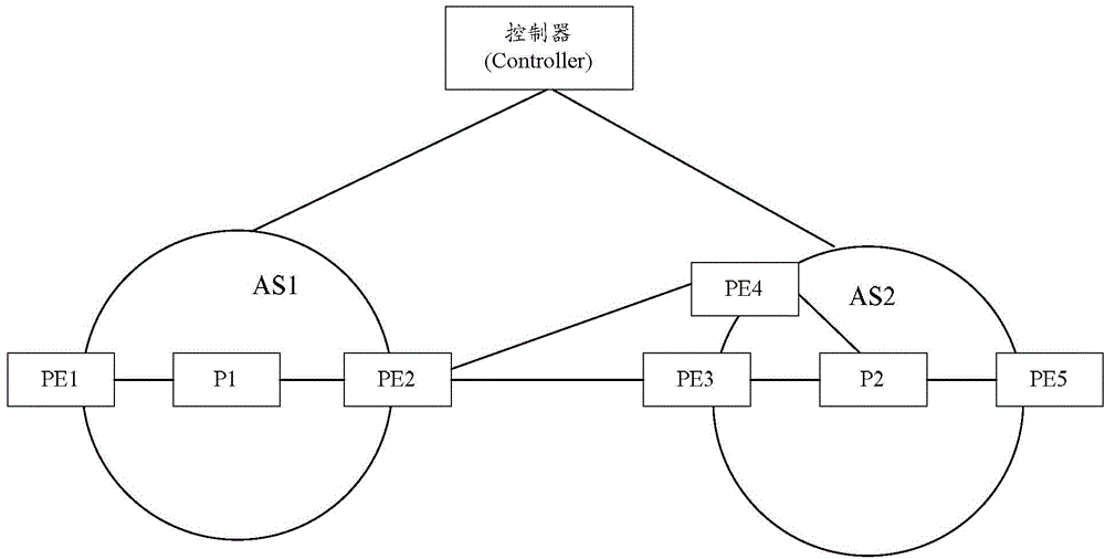
[0005] However, in cross-domain scenarios, especially VPNOptionC cross-domain scenarios, it is necessary to build a public network tunnel between the source PE and the sink PE. If the public network tunnel belongs to the SR network, there is no corresponding technical solution to Realize the interaction of SR information across domains, so it is impossible to establish an SR network

Method used


Image

  • SR information acquisition method and route segment network establishment method
  • SR information acquisition method and route segment network establishment method
  • SR information acquisition method and route segment network establishment method

Examples


Embodiment Construction

[0062] In order to make the purpose, technical solution and advantages of the present invention more clear, the embodiments of the present invention will be described in detail below in conjunction with the accompanying drawings. It should be noted that, in the case of no conflict, the embodiments in the present application and the features in the embodiments can be combined arbitrarily with each other.

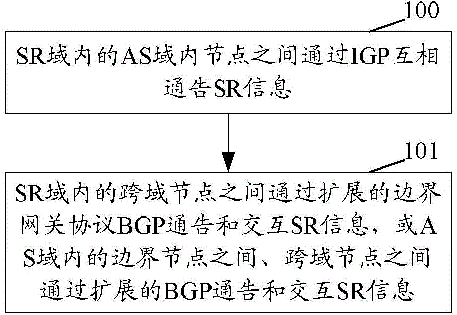
[0063] figure 1 It is a flowchart of the SR information acquisition method of the present invention, such as figure 1 shown, including:

[0064] Step 100: Nodes in the AS domain in the SR domain notify each other of SR information through the IGP.

[0065] The implementation of this step belongs to the well-known technology of those skilled in the art, and the specific implementation is not used to limit the protection scope of the present invention, so it will not be repeated here.

[0066] Step 101: The inter-domain nodes in the SR domain advertise and exchange SR inform...


PUM


Abstract

The invention discloses an information acquisition method and a route segment network establishment method. The method comprises the steps of mutually announcing the SR information among nodes in the AS domain within the SR domain; announcing the SR information among cross-domain nodes in the SR domain through extended BGP announcements and the interactive SR information, or among boundary nodes and cross-domain nodes in the AS domain through extended BGP announcements and the interactive SR information. According to the invention, the interaction of the SR information in the cross-domain condition can be realized among boundary nodes in different AS domains in the SR domain through extended BGP announcements and the SR information among cross-domain nodes in interactive SR domains among different AS domains. Furthermore, based on the SR information acquisition method, an SR information list (SR list) can be acquired by a head node. The generated SR list is carried outside a data message. The data message is forwarded through a shortest path according to the SR information designated by the SR list. Therefore, an end-to-end SR network can be established.

Description

technical field [0001] The invention relates to segment routing (SR, SegmentRouting) technology, in particular to a method for acquiring SR information and a method for establishing a segment routing network. Background technique [0002] A typical service bearing network includes a customer edge (CE) router, a provider edge (PE) router, a provider backbone (P) router, and a route reflector (RR). Usually open shortest path first (OSPF, OpenShortestPathFirst) protocol / intermediate system to intermediate system routing protocol (IS-IS, IntermediateSystemtoIntermediateSystemRoutingProtocol) as the interior gateway protocol (IGP, InteriorGatewayProtocol), using BGP-4 multi-protocol extended border gateway protocol (MP-BGP, where BGP is Border Gateway Protocol) transfers virtual private network (VPN, Virtual Private Network) information, uses Label Distribution Protocol (LDP) to distribute labels and uses traffic engineering-based extension Resource Reservation Protocol (RSVP-T...

Claims


Application Information

Patent Timeline
IPC IPC(8): H04L12/715H04L12/741H04L45/50H04L45/74
CPCH04L45/04H04L45/50H04L45/72
Inventor 陈然彭少富许永帆唐寅
Owner ZTE CORP
Learn More