
Extraction of arc length from voltage and current feedback

A technology of arc length and voltage, applied in arc welding equipment, manufacturing tools, welding equipment, etc.

Active Publication Date: 2016-06-01
ILLINOIS TOOL WORKS INC
View PDF8 Cites 9 Cited by
  • Summary
  • Abstract
  • Description
  • Claims
  • Application Information

AI Technical Summary

Problems solved by technology

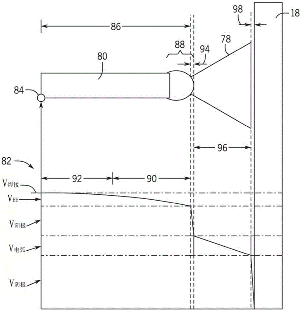
However, the arc voltage across the arc length may only be a fraction of the welding voltage between the torch and workpiece

Method used


Image

  • Extraction of arc length from voltage and current feedback
  • Extraction of arc length from voltage and current feedback
  • Extraction of arc length from voltage and current feedback

Examples


Embodiment Construction

[0018] One or more specific embodiments of the invention are described below. In an effort to provide a precise description of these embodiments, not all features of an actual implementation are described in the specification. It should be understood that in developing any such actual implementation, such as in any engineering or design project, numerous implementation-specific decisions must be made to achieve the developer's specific objectives, such as compliance with system-related and business-related constraints conditions, which may vary from implementation to implementation. Furthermore, it should be appreciated that such a research and development effort might be complex and time consuming, but would nevertheless be a routine undertaking of design, fabrication, and production for those having the benefit of this disclosure.

[0019] When introducing various embodiments of the present invention, the articles "a," "an," "the," and "said" are intended to mean that there...


PUM


Abstract

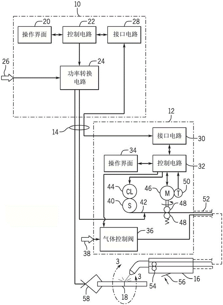
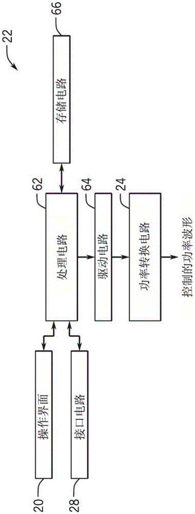
A method of controlling a welding system includes controlling a weld current supplied to an electrode at a current ramp rate and determining an arc length based at least in part on the controlled weld current and a changing arc voltage. The arc length includes a distance between the electrode and a workpiece, and the arc voltage includes a voltage between the electrode and the workpiece.

Description

Background technique [0001] The present invention relates generally to welding systems and, more particularly, to controlled gas metal arc welding (GMAW) welding systems, also known as metal inert gas (MIG) welding systems. [0002] An arc welding system typically includes a power supply that applies current to an electrode to cause an arc to pass between the electrode and workpiece, thereby heating the electrode and workpiece to establish a weld. In many systems, such as gas metal arc welding (GMAW), the electrode consists of a welding wire that is fed through a welding torch. As the electrode is heated by the arc, the electrode melts and bonds to the molten metal of the workpiece to form a weld. [0003] Advanced forms of MIG welding are based on the generation of pulsed power in the welding power source, which may be referred to as pulsed gas metal arc welding (GMAW-P). That is, various pulsing regimes can be implemented in which current pulses and / or voltage pulses are c...

Claims


Application Information

Patent Timeline
IPC IPC(8): B23K9/09B23K9/095B23K9/10B23K9/12B23K9/173
CPCB23K9/091B23K9/0956B23K9/125B23K9/173B23K9/1062B23K9/0953
Inventor 理查德·马丁·哈奇森
Owner ILLINOIS TOOL WORKS INC
Learn More