Cerebrospinal fluid drainage device and intracranial pressure monitoring system

A cerebrospinal fluid and intracranial pressure technology, applied in the field of medical devices, can solve problems such as patient safety hazards, malfunctions, and impact on the accuracy of intracranial pressure, so as to avoid cross-infection and ensure accuracy

Inactive Publication Date: 2016-06-08
王学建
View PDF8 Cites 15 Cited by
  • Summary
  • Abstract
  • Description
  • Claims
  • Application Information

AI Technical Summary

Problems solved by technology

[0004] The problem in the clinical use of the previous intracranial pressure monitoring system is that although a guiding tube is used to connect the cerebrospinal fluid drainage tube and the sensor to avoid the inflow of cerebrospinal fluid from polluting the sensor as much as possible, in order to realize the transmission of pressure, it is used to communicate with the pressure sensor. The guide tube 2 connected to the sensor 4 is directly connected with the drainage tube 1. When the gas in the tube expands with heat and contracts with cold, or the external pressure increases due to the shock generated during use, or the pressure of the cerebrospinal fluid increases, the flow in the guide tube will be caused. When the gas is compressed, there is still the possibility and possibility of cerebrospinal fluid being sucked back into the guide tube 2 (cerebrospinal fluid backflow). Once the cerebrospinal fluid flows from the guide tube to the pressure sensor 4, the sensor sensitivity will decrease or even fail. It affects the accuracy of the measured intracranial pressure and brings safety hazards to patients. In addition, the backflow of cerebrospinal fluid will contaminate the pressure sensor and easily cause cross-infection

Method used


Image

  • Cerebrospinal fluid drainage device and intracranial pressure monitoring system
  • Cerebrospinal fluid drainage device and intracranial pressure monitoring system
  • Cerebrospinal fluid drainage device and intracranial pressure monitoring system

Examples


Embodiment Construction

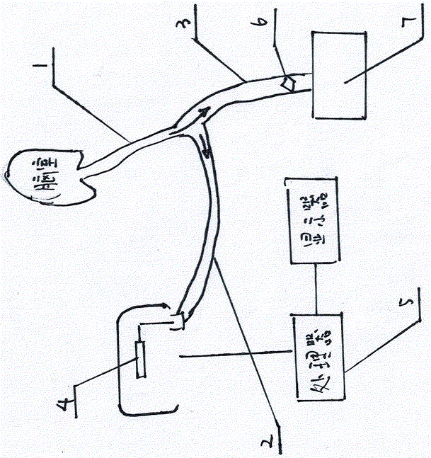
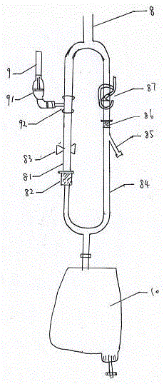
[0020] figure 2 It is a structural schematic diagram of an embodiment of the cerebrospinal fluid drainage device of the present invention; please refer to figure 2 , the present embodiment provides a cerebrospinal fluid drainage device, comprising a cerebrospinal fluid drainage tube and a drainage bag for collecting the liquid in the cerebrospinal fluid drainage tube, the cerebrospinal fluid drainage tube is connected with a guide tube 9 for connecting to a pressure sensor; A first control valve 83 is set on the cerebrospinal fluid drainage tube and between the guide tube 9 and the drainage bag 10; a buffer balloon 91 is set on the guide tube 9 and near the connection between the guide tube 9 and the cerebrospinal fluid drainage tube.

[0021] Specifically, the cushioning airbag 91 may be circular or other irregular three-dimensional shapes, and an accommodating cavity with an appropriate volume may be formed inside it. And the cushioning airbag 91 can be integrally formed ...


PUM


Abstract

The invention provides a cerebrospinal fluid drainage device and an intracranial pressure monitoring system. The cerebrospinal fluid drainage device comprises a cerebrospinal fluid drainage tube and a drainage bag used for collecting fluid in the cerebrospinal fluid drainage tube, a guide tube used for being connected with a pressure sensor is communicated on the cerebrospinal fluid drainage tube, a first control valve is arranged at a position, between the guide tube and the drainage bag, of the cerebrospinal fluid drainage tube, and a buffering airbag is arranged at a position, close to a joint of the guide tube and the cerebrospinal fluid drainage tube, of the guide tube. Through the buffering airbag arranged on the guide tube, cerebrospinal fluid in the cerebrospinal fluid drainage tube can be effectively avoided being sucked back into the guide tube, so that failing of the pressure sensor caused by the fact that the cerebrospinal fluid flows back to the pressure sensor can be effectively prevented, accuracy of intracranial pressure detected by the pressure sensor is guaranteed, the pressure sensor is prevented from being polluted by the cerebrospinal fluid, and cross infection caused by reuse of the sensor is avoided.

Description

technical field [0001] The invention relates to the field of medical devices, in particular to a cerebrospinal fluid drainage device and an intracranial pressure monitoring system. Background technique [0002] Under normal conditions, the intracranial pressure of the human body is in a stable range, such as 80-180mmHg for adults, but many diseases can cause increased intracranial pressure in clinical practice, and the causes can be divided into acute factors and chronic factors. Acute factors include brain tissue swelling, intracranial hemorrhage, obstructive hydrocephalus and other factors; chronic factors include tumor growth and other factors, continuous increase in intracranial pressure can cause intracranial hypertension, and severe cases lead to brain herniation, which can be life-threatening. For the nursing of some trauma patients, measuring and monitoring the change of their intracranial pressure is also an important link to prevent complications, guide whether eme...

Claims


Application Information

Patent Timeline
Patent Type & Authority Applications(China)
IPC IPC(8): A61M1/00A61B5/03
CPCA61M1/0011A61B5/032A61M2202/0464A61M1/69A61M1/84A61M2202/0014A61B5/031A61M27/006
Inventor 王学建
Owner 王学建
Why Eureka
Try Eureka