Liquid treatment equipment

A technology for liquid treatment and treatment equipment, applied in water/sewage treatment, heating water/sewage treatment, water/sludge/sewage treatment, etc. Improved distillation and concentration efficiency, increased heat transfer efficiency, and low operating costs

A technology for liquid treatment and treatment equipment, applied in water/sewage treatment, heating water/sewage treatment, water/sludge/sewage treatment, etc. Improved distillation and concentration efficiency, increased heat transfer efficiency, and low operating costs

CN105641963AActive Publication Date: 2016-06-08HIMILE MECHANICAL MFG

Image

  • Liquid treatment equipment
  • Liquid treatment equipment
  • Liquid treatment equipment

Examples


Embodiment Construction

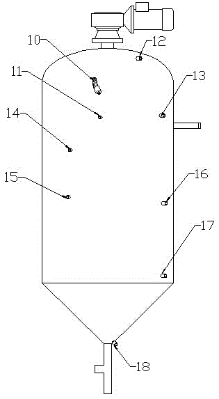
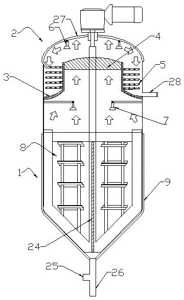
[0042] Examples such as figure 1 As shown, a liquid processing device includes an evaporation chamber 1, a condensation chamber 2 is arranged on the evaporation chamber 1, the evaporation chamber 1 is adjacent to the condensation chamber 2, and the evaporation chamber 1 and the condensation chamber 2 are integrally structured.

[0043] The evaporating chamber 1 and the condensing chamber 2 are separated by an interlayer 3 , and the interlayer 3 is used to avoid heat exchange between the evaporating chamber 1 and the condensing chamber 2 .

[0044] A vertical cylindrical passage is arranged in the middle of the interlayer 3, and the vertical cylindrical passage can ensure that the steam in the evaporation chamber 1 enters the condensation chamber 2 smoothly.

[0045] An annular cavity is formed between the interlayer 3 and the inner wall of the condensation chamber 2 to ensure that the condensed liquid will not flow back into the evaporation chamber 1 .

[0046] The liquid tr...


PUM


Abstract

The invention discloses liquid treatment equipment. The liquid treatment equipment comprises an evaporation chamber, and a condensation chamber is arranged on the evaporation chamber. According to the technical scheme, compared with common distillation and concentration treatment equipment, the evaporation and condensation integrated design is adopted for the liquid treatment equipment, so that the liquid treatment equipment is compact in structure, and space occupied by the liquid treatment equipment is reduced by about 20% or above compared with that occupied by present common equipment; a scraper is arranged inside the equipment, so that the problem that scale is formed on the inner wall of the evaporation chamber in the evaporation process and is difficult to remove is solved.

Description

technical field [0001] The invention relates to the technical field of distillation, concentration and crystallization, in particular to a liquid processing device. Background technique [0002] Traditional distillation equipment can be used for distillation purification or concentrated crystallization, etc., but the current distillation equipment is large in size, complicated in connection, easy to scale, high in energy consumption, insufficient in solution mixing, low in efficiency in distillation and concentration, and requires a fixed location for actual production. Bring great inconvenience and higher cost. Contents of the invention [0003] The technical problem to be solved by the present invention is to provide a liquid treatment equipment with simple and compact structure, small space occupation, low energy consumption, more uniform solution mixing and high distillation and concentration efficiency. [0004] In order to solve the above technical problems, the pre...

Claims


Application Information

Patent Timeline
08 Jun 2016
Publication
CN105641963A
IPC
B01D3/10; B01D3/42; B01D1/00; B01D1/30; C02F1/04
CPC
B01D1/00; B01D1/0082; B01D1/30; B01D3/10; B01D3/42; C02F1/04; C02F1/048
Inventors
李庆喜