Stirring mechanism for electro-deposition

A stirring mechanism and electrodeposition technology, which is applied in the direction of electrolysis process, electrolysis components, cells, etc., can solve the problems of not achieving the effect, and achieve the effect of simple structure, low cost, high strength and uniform stirring effect

Inactive Publication Date: 2016-06-08
HENAN POLYTECHNIC UNIV
View PDF4 Cites 8 Cited by
  • Summary
  • Abstract
  • Description
  • Claims
  • Application Information

AI Technical Summary

Problems solved by technology

Although a variety of cathode stirring devices have been developed so far, they still have not achieved very satisfactory results.

Method used


Image

  • Stirring mechanism for electro-deposition
  • Stirring mechanism for electro-deposition

Examples


Embodiment Construction

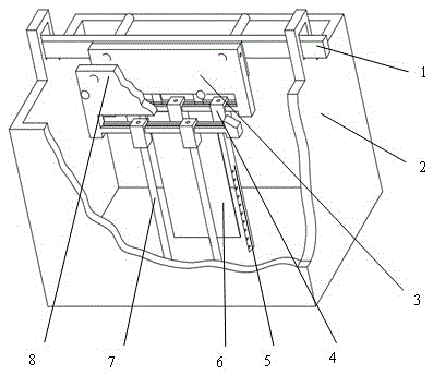
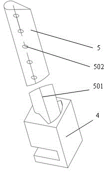
[0020] Combine below figure 1 and figure 2 The implementation of the present invention is further described in detail: a stirring mechanism for electrodeposition, which includes a horizontal reciprocating beam 1, a near-cathode suspension beam 3, a near-cathode stirring paddle 5, a far-cathode suspension beam 8, and a far-cathode stirring paddle 7 and the limit seat 4; the horizontal reciprocating beam 1 is arranged above the electrolytic cell 2; the near-cathode suspension beam 3 and the far-cathode suspension beam 8 are fixed on the horizontal reciprocating beam 1 with bolts; the near-cathode suspension beam 3 is close to the horizontal The reciprocating beam 1, the distance between the near-cathode suspension beam 3 and the far-cathode suspension beam 8 is 40mm; the limit seat 4 can be fixed on the lower end of the near-cathode suspension beam 3 and the far-cathode suspension beam 8 by bolts; The upper end is assembled and connected with the limit seat 4 through a rolling...


PUM


Abstract

The invention discloses a stirring mechanism for electro-deposition which comprises an electro-deposition tank, a cathode, a cathode moving mechanism and a stirring mechanism body. The stirring mechanism body comprises near cathode stirring paddles, far cathode stirring paddles, a near cathode suspension beam, a far cathode suspension beam and limiting seats. When the stirring mechanism works, a horizontal reciprocating moving beam drives the near cathode stirring paddles connected with the near cathode suspension beam and the far cathode stirring paddles connected with the far cathode suspension beam to do horizontal synchronous reciprocating movement; under the dual actions of the near cathode stirring paddles and the far cathode stirring paddles in the mechanism, an electrolyte solution near cathode planes and in the whole electro-deposition tank can be stirred uniformly at high intensity. The stirring mechanism for electro-deposition greatly improves the uniformity of thickness distribution of a deposition layer and is simple in structure and low in cost.

Description

technical field [0001] The invention relates to the technical field of electrodeposition production equipment, in particular to a stirring mechanism for electrodeposition. Background technique [0002] At present, in industrial production, air stirring or cathode moving devices are mostly used for stirring the electrolyte of electrodeposition (including electroplating and electroforming). These two stirring methods have their own advantages and disadvantages. Generally speaking, it is easier to obtain a uniform mass transfer distribution on the cathode surface when the cathode is moved and stirred. However, the intensity of cathode moving and stirring is generally not high, and the global stirring effect on the entire electrodeposition tank is relatively low, resulting in generally low deposition rate and thickness distribution uniformity. The main reason is that the conventional cathode moving and stirring only uses the shearing action between the workpiece (cathode) and t...

Claims


Application Information

Patent Timeline
Patent Type & Authority Applications(China)
IPC IPC(8): C25D21/10
CPCC25D21/10
Inventor 陈东海张艳华明平美陈丹佛赵云龙李欣潮陈月涛赵晨昊秦歌
Owner HENAN POLYTECHNIC UNIV
Why Eureka
Try Eureka