
Detection method and system of surface thickness and planeness of rotary target

A detection method and detection system technology, applied in the direction of measuring devices, instruments, optical devices, etc., can solve the problems of errors, inability to directly reflect the thickness of the rotating target spraying target material, and the difficulty of directly detecting the thickness of the spraying target material, etc., to achieve The effect of improving precision and accuracy

Inactive Publication Date: 2016-06-08
广州市尤特新材料有限公司
View PDF8 Cites 15 Cited by
  • Summary
  • Abstract
  • Description
  • Claims
  • Application Information

AI Technical Summary

Problems solved by technology

At present, the method of detecting the thickness of the target is to stop the machine, and use random sampling on the sprayed target to measure the thickness of the target. However, this detection method cannot directly reflect the thickness of the sprayed target on the entire rotating target; and manual detection is used. It is easy to introduce errors, and the shutdown detection will affect the efficiency of spraying production and increase the cost of spraying
In addition, during the spraying production process, the high-energy particle flow will emit a strong glow, making it difficult to directly detect the thickness of the spraying target

Method used


Image

  • Detection method and system of surface thickness and planeness of rotary target
  • Detection method and system of surface thickness and planeness of rotary target
  • Detection method and system of surface thickness and planeness of rotary target

Examples


Embodiment Construction

[0030] The specific implementation manners of the present invention will be further described in detail below in conjunction with the accompanying drawings and embodiments. The following examples are used to illustrate the present invention, but are not intended to limit the scope of the present invention.

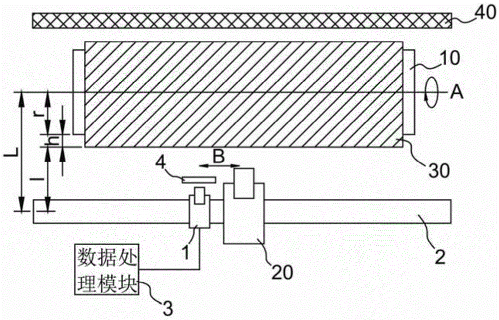
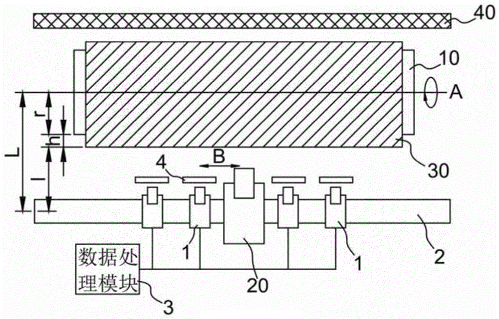
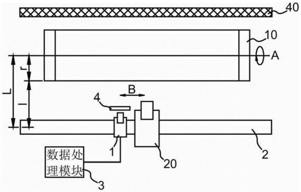
[0031] figure 1 Schematically shows the working principle of the detection system according to an embodiment of the present invention, wherein, before spraying, the distance measuring module 1 is installed on one side of the revolving body 10, and the baffle 40 is installed on the other side of the revolving body 10, And the distance between the ranging module 1 and the axis A of the rotating body 10 is a fixed value L, and the ranging module 1 is driven by the driving module 2, so that the ranging module 1 can reciprocate along the axial direction of the rotating target 1 (direction B) , preferably the distance measuring module 1 and the spray gun 20 are arranged on the ...


PUM


Abstract

The invention relates to the field of surface spraying and discloses a detection method and system of surface thickness and planeness of a rotary target. A distance measuring module moves synchronously along with a spraying gun in the axial direction of the rotary target; the distance measuring module is used for detecting a distance l between a certain point of the surface of a coating and the distance measuring module in real time; the distance measuring module is used for transmitting measured data to a data processing module; and the data processing module is used for calculating the thickness of the surface coating in real time according to an equation h=L-r-1. According to the detection method and system, disclosed by the invention, the surface thickness or the planeness of the rotary target can be detected in real time in a spraying production process of the rotary target, so as to avoid a condition that the thickness or the planeness of the surface coating is detected manually by halting is avoided, and a surface spraying speed is not influenced; manual errors, introduced by manual detection, can be avoided by adopting an optical detection module to detect the surface of the rotary target in real time, and the detection precision and the detection accuracy are improved; and a non-contact type detection manner of optical detection is adopted, so that the surface of the detected coating is not damaged, and the surface quality of the coating is not influenced.

Description

technical field [0001] The invention relates to the field of surface spraying, in particular to a detection method and detection system for the surface thickness and flatness of a rotating target. Background technique [0002] In order to protect the surface of the rotating target from corrosion or to have certain characteristics, the target is generally sprayed onto the surface of the rotating target by spraying technology. The deposition thickness of each spraying target is generally 20-50 microns. If it is necessary to spray a target with a thickness of 6mm-20mm on the surface of the rotating target, the spray gun needs to be sprayed back and forth 50-500 times, so that the spraying process generally lasts 10-20 Hour. [0003] Due to the long spraying process, the raw materials, working air pressure, powder feeding amount, mechanical walking parameters and external factors during the spraying process will all affect the surface quality and spraying efficiency of the spra...

Claims


Application Information

Patent Timeline
IPC IPC(8): G01B11/06G01B11/30
CPCG01B11/06G01B11/0616G01B11/30
Inventor 江永钊沈艳斌
Owner 广州市尤特新材料有限公司
Learn More