
Method for determining fatigue life index of hydraulic conduit

A technology for determining fatigue life and indicators, applied in special data processing applications, measuring devices, instruments, etc., can solve the problem that projects cannot be directly adopted, cannot truly reflect the fatigue life of thin-walled hydraulic metal conduits, and have not found thin-walled hydraulic metal conduits Fatigue life curve measurement method and related data to achieve the effect of evaluation rationality and data authenticity

Active Publication Date: 2016-06-08
XIAN AIRCRAFT DESIGN INST OF AVIATION IND OF CHINA
View PDF6 Cites 19 Cited by
  • Summary
  • Abstract
  • Description
  • Claims
  • Application Information

AI Technical Summary

Problems solved by technology

[0006] At present, the determination of the fatigue life curve of the material is all measured on the standard test piece (solid metal material, 200mm straight pipe section), and the given material fatigue life curve cannot truly reflect the actual use environment of the thin-walled hydraulic metal conduit (high vibration, High pressure pulsation) in the fatigue life, engineering can not be directly used
Moreover, the measurement method and related information of the fatigue life curve of thin-walled hydraulic metal conduits have not been found in the public material manual.

Method used


Image

  • Method for determining fatigue life index of hydraulic conduit
  • Method for determining fatigue life index of hydraulic conduit
  • Method for determining fatigue life index of hydraulic conduit

Examples


Embodiment

[0039] The following takes the determination process of the fatigue life index of the high-pressure pipeline at the outlet of the engine-driven pump of a hydraulic system of a certain type of machine as an example to further explain this scheme:

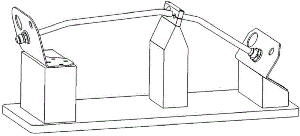
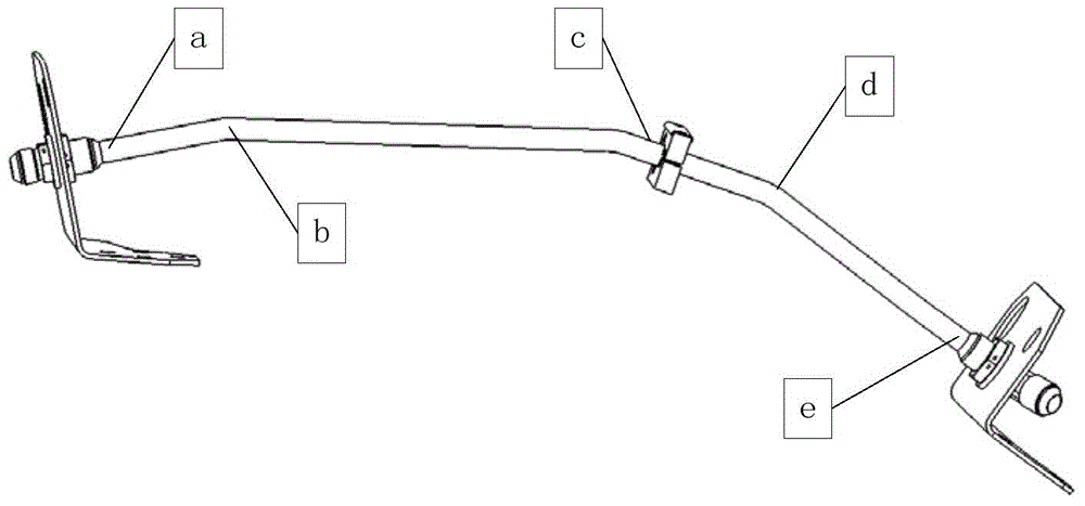
[0040] 1) Take the short elbow structure actually installed in the hydraulic pipeline of a certain type of aircraft. Its inner diameter is 12mm, outer diameter is 14mm, and its length is about 580mm. It is restrained by three points and filled with 21MPa No. 15 aviation oil. Considering the test fixture together, the geometric model established in ANSYSWorkbench is as follows figure 1 shown.

[0041] The contacts are all bound, and the grid is divided, with a total of 49939 elements and 271682 nodes.

[0042] Set boundary conditions: apply fluid-solid coupling surface constraints to the interface between fluid and solid. A pressure constraint of 21 MPa is imposed on both ends of the fluid surface to simulate the fluid pressure situ...


PUM


Abstract

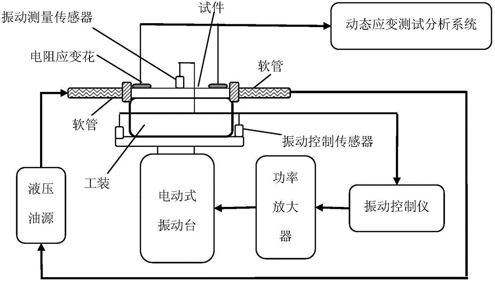
The invention, which belongs to the hydraulic system of the airplane, discloses a method for determining a fatigue life index of a hydraulic conduit. The method comprises: (1), a monitoring point easily causing a fatigue fracture is found out; (2), a tested piece the same as that of an airplane is employed; (3), a rated working pressure of a system is applied into the tested piece; (4), a foil gauge and an acceleration sensor are loaded at the monitoring point; (5), an output frequency of a vibrating table is controlled to be an inherent frequency of the tested piece; (6), output amplitudes of the vibrating table are controlled to be set successively in a range from 0,75 sigma b to sigma -1 in a descending order according to stress values generated on the conduit, a stress value and an acceleration value at the monitoring point are measured, and the number of times of cycling of the tested piece in a fracture mode is recorded; (7), according to the stress value and the number of times of cycling or the acceleration value and the number of times of cycling, a fatigue life curve of the tested piece is fitted; and (8), a stress value or acceleration value of a position close to a horizontal line on the fatigue life curve is a fatigue life index control value of a hydraulic conduit. With the method, reasonability, reliability, and durability of the airplane hydraulic system pipeline design can be evaluated effectively.

Description

technical field [0001] The invention belongs to an aircraft hydraulic system, in particular to a method for determining a fatigue life index of a hydraulic conduit. Background technique [0002] The fatigue life (stress level) control of hydraulic conduit is the key to ensure the long-term safe and reliable operation of the hydraulic system. GJB1396-1992 "Aircraft Hydraulic Emergency Pneumatic System Test Requirements and Methods" clearly requires that the hydraulic system should be subjected to vibration measurement to verify that there is no harmful resonance state caused by the operation of the hydraulic system under various operating conditions of the aircraft. This requirement is only a qualitative requirement, not a quantitative one. [0003] In the American standard and European standard systems, there are vibration test requirements for hydraulic systems. For example, SAEAS5440 "Military Aircraft Hydraulic System Design and Installation Requirements" requires that ...

Claims


Application Information

Patent Timeline
IPC IPC(8): G01M13/00G01M7/02G06F19/00
Inventor 罗旭东苏岚刘红周世刚江辉军
Owner XIAN AIRCRAFT DESIGN INST OF AVIATION IND OF CHINA
Learn More