Method for testing glass by using worm wheel turntable rack photography and circular corner clamp plates

A platform and worm gear technology, which is applied in the field of tempered glass testing and inspection, can solve the problems of operator injury, non-square, and no unified fixed splint, etc., achieve the effect of standardization and uniformity, and change labor intensity

Inactive Publication Date: 2016-06-08
WENZHOU ECONOMIC TECH DEV ZONE BINHAI XIONGJIE ELECTROMECHANICAL RES & DEV STUDIO
View PDF5 Cites 14 Cited by
  • Summary
  • Abstract
  • Description
  • Claims
  • Application Information

AI Technical Summary

Problems solved by technology

Chinese patent application number: 2009203050079, tempered glass falling ball test bench, in order to solve the problem of glass fragments splashing everywhere when tempered glass is used for experiments, the method of supporting the frame box is adopted. Although the glass fragments can be collected effectively, it is inconvenient to read the glass fragments. , and the installation efficiency of continuous multi-piece tempered glass is low
Due to the diversity of automobile designs, the glass on the corresponding car is becoming more and more complex. The shape of the glass is often not square or rectangular, but parallelogram or trapezoidal glass can be found everywhere. In the past, there was no detection of this kind of irregular quadrilateral glass. Unified fixed splints, only use scotch tape paper or other methods to restrain the glass perimeter, or cover a layer of film on the tempered glass to prevent glass fragments from splashing
At the same time, the adhesive tape is also likely to be broken by the force of the tempered glass explosion, causing the operator to be injured. Therefore, it is very necessary to improve the tempered glass fragment test device

Method used


Image

  • Method for testing glass by using worm wheel turntable rack photography and circular corner clamp plates
  • Method for testing glass by using worm wheel turntable rack photography and circular corner clamp plates
  • Method for testing glass by using worm wheel turntable rack photography and circular corner clamp plates

Examples


Embodiment Construction

[0071] Describe the present invention in detail below in conjunction with accompanying drawing and specific embodiment:

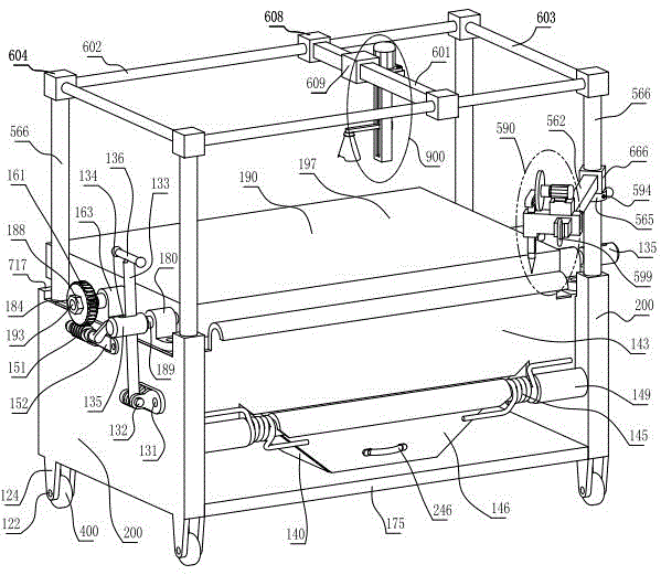
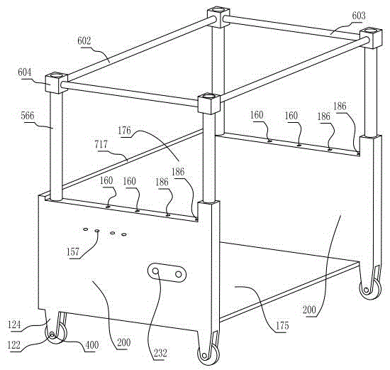
[0072] figure 1 , figure 2 , Figure 5 , Figure 10 , Figure 11 , Figure 12 , Figure 13 , Figure 14 , Figure 15 and Figure 17In this method, the method of detecting glass with a round corner splint using a camera on a worm gear turntable rack, the overall frame includes a support side plate 200, a rear shear plate 176, a bottom shear plate 175, and four upper circular columns 566, and the support side plates on both sides The two upper circular columns 566 are respectively fixed on the 200, the upper ends of the four upper circular columns 566 are fixed with column ends 604, and the four column ends 604 are respectively fixed with two horizontal horizontal bars 602 and two longitudinal horizontal bars. rod 603;

[0073] The upper planes of the supporting side plates 200 on both sides are respectively fixed with a platform support 163 and a ...


PUM

PropertyMeasurementUnit
thicknessaaaaaaaaaa
widthaaaaaaaaaa
tensile strengthaaaaaaaaaa

Abstract

The invention relates to a tempered glass testing method, in particular to a method for testing glass by using worm wheel turntable rack photography and circular corner clamp plates. Modifications include: one, an assembly process includes a clamp plate assembly process and a machine assembly process; two, a tempered glass fragmentation test includes the following steps: (one), a worm cranking handle at one end of a worm shaft is cranked by hand so that a test top plate is horizontal; (two), first, second, third and fourth clamp plates equal in structural size are placed on the test top plate; (three), a trapezoidal glass plate to be tested is placed on the test top plate within a surrounded space; (four), an impact motor is started to break the trapezoidal glass plate; (five), a photography motor is started to take photos and send fragment photos to a computer processing center; (six), the second and third clamp plates are moved so that tempered glass fragments can be conveniently cleared and dropped into a glass fragment recycling container.

Description

technical field [0001] The invention relates to a test and inspection method for tempered glass, in particular to a test and inspection system equipped with an industrial camera instead of manual operation, which uses a worm gear turntable and rack camera to take pictures of a circular corner plywood inspection method for glass. Background technique [0002] G0rd0nGaileG published the article "Aut0matedGlassFragmentati0nAnalysis" in 1996, discussing the detection algorithm of glass fragments. This document involves two key technologies: (1) image acquisition technology. Under a piece of photosensitive paper imaged by glass shards, light sources were applied from two different angles, and an original digital image of the shadow of the crack line of the shards was collected. In this way, due to the use of light sources at different angles, the two images collected must be different. In one of the images, the position of the inconspicuous seam line due to lighting may be mor...

Claims


Application Information

Patent Timeline
Patent Type & Authority Applications(China)
IPC IPC(8): G01N3/317G01N3/04G01N3/06
CPCG01N3/04G01N3/068G01N3/317G01N2203/0087
Inventor 陈丹青
Owner WENZHOU ECONOMIC TECH DEV ZONE BINHAI XIONGJIE ELECTROMECHANICAL RES & DEV STUDIO
Why Eureka
Try Eureka