Mobile terminal positioning method, acoustic positioning transmitter-receiver, mobile terminal and mobile terminal positioning system

A sonic positioning and mobile terminal technology, applied in radio wave measurement systems, positioning, instruments, etc., can solve the problems that signals cannot be received correctly, increase the cost of mobile terminals, and have low positioning accuracy

Inactive Publication Date: 2016-06-08
上海酷远物联网科技有限公司
View PDF4 Cites 17 Cited by
  • Summary
  • Abstract
  • Description
  • Claims
  • Application Information

AI Technical Summary

Problems solved by technology

The principles of WiFi, BlueTooth (Bluetooth) and ZigBee positioning technologies are generally divided into the network side and the transmitting side, but they all use the degree of signal strength attenuation to achieve positioning. The biggest problem with these two positioning technologies is that the signals are often affected by various factors in the environment. Influences such as wall blocking, reflection and diffraction, people walking, time, weather, etc., cause signal drift, resulting in the signal not being received correctly, and the highest positioning accuracy can only reach 1m, which leads to these indoor positioning products In particular, ZigBee positioning technology also requires a large number of sensors to form a network, which affects the expansion of the entire indoor positioning product
The principle of RFID positioning is to locate indoor users by deploying multiple positioning signal sources or positioning signal tags indoors, using a strength or delay calculation method similar to outdoor pos

Method used


Image

  • Mobile terminal positioning method, acoustic positioning transmitter-receiver, mobile terminal and mobile terminal positioning system
  • Mobile terminal positioning method, acoustic positioning transmitter-receiver, mobile terminal and mobile terminal positioning system
  • Mobile terminal positioning method, acoustic positioning transmitter-receiver, mobile terminal and mobile terminal positioning system

Examples


Embodiment Construction

[0095] In order to make the purpose and features of the present invention more obvious and understandable, the specific implementation of the present invention will be further described below in conjunction with the accompanying drawings. However, the present invention can be implemented in different forms and should not be limited to the described embodiments.

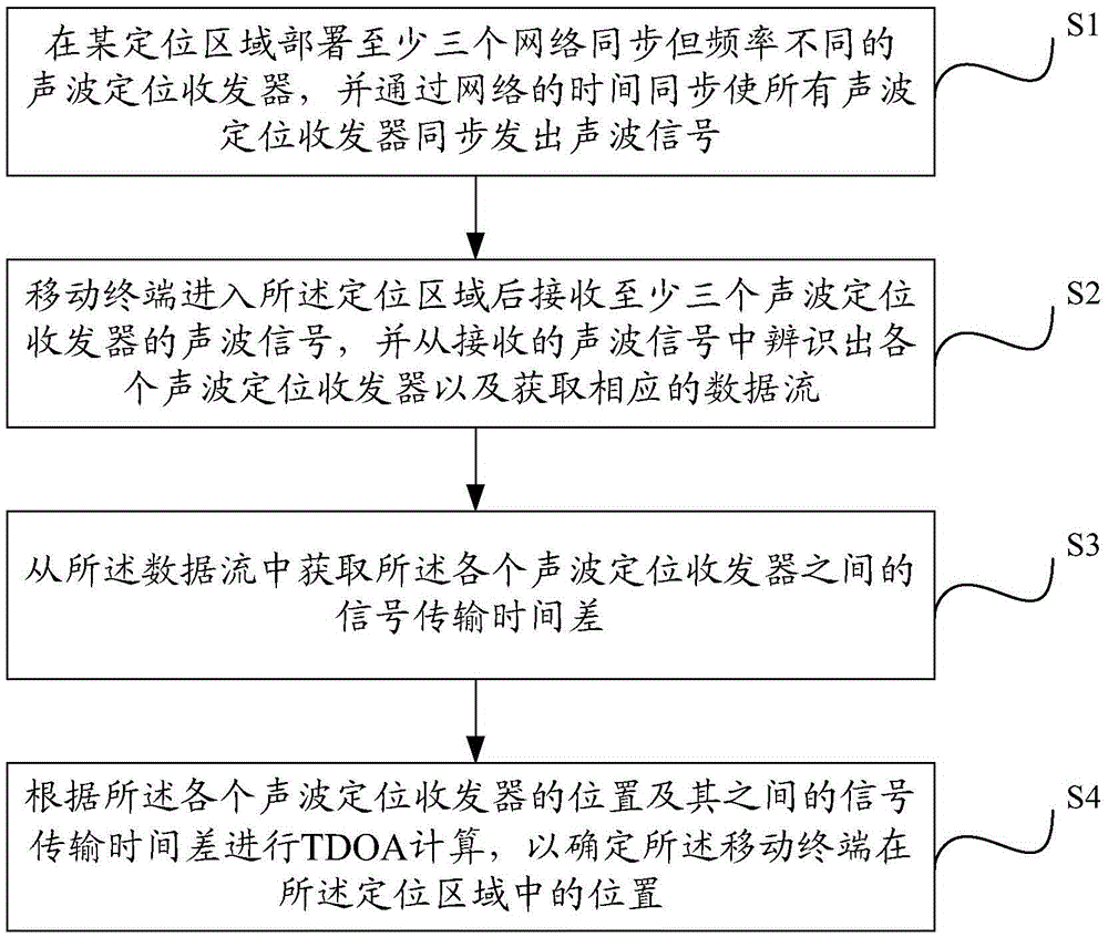
[0096] Please refer to figure 1 , the present invention provides a mobile terminal positioning method, comprising the following steps:

[0097] S1. Deploy at least three acoustic wave positioning transceivers with synchronous networks but different frequencies in a certain positioning area, and make all acoustic wave positioning transceivers send out acoustic signals synchronously through time synchronization of the network;

[0098] S2. After the mobile terminal enters the positioning area, it receives sound wave signals from at least three sound wave positioning transceivers, and identifies each sound wave positioni...


PUM


Abstract

The invention provides a mobile terminal positioning method, an acoustic positioning transmitter-receiver, a mobile terminal and a mobile terminal positioning system. At least three acoustic positioning transmitter-receivers with synchronized networks and different frequencies are arranged at a certain positioning region, and acoustic signals are synchronously transmitted to the mobile terminal by all the acoustic positioning transmitter-receivers through network time synchronization; after the mobile terminal enters the positioning region, the acoustic signals of the at least three acoustic positioning transmitter-receivers are received, and each acoustic positioning transmitter-receiver is identified from the received acoustic signals and corresponding data flows are acquired; a signal transmission time difference between each two acoustic positioning transmitter-receivers is acquired from the data flows; and TDOA (Time Difference of Arrival) calculation is carried out according the position of each acoustic positioning transmitter-receiver and the transmission time difference between each two acoustic positioning transmitter-receivers so as to determine the position of the mobile terminal in the positioning region. According to the technical scheme provided by the invention, the positioning cost of the positioning region is reduced and the positioning precision and reliability of the mobile terminal are improved.

Description

technical field [0001] The invention relates to the technical field of mobile terminal positioning, in particular to a mobile terminal positioning method, an acoustic wave positioning transceiver, a mobile terminal and a system. Background technique [0002] With the rapid development of global satellite positioning technology, geographic information system and Internet technology, the rapid increase of data services and multimedia services, the rapid popularization of communication networks and mobile terminal equipment, people's demand for indoor location services is also increasing. Precise indoor location services can efficiently manage available space and inventory materials, and can navigate police, firefighters, and medical staff to complete specific indoor tasks. Therefore, indoor positioning, that is, realizing position positioning in an indoor environment, has broad application prospects and is gradually becoming a research hotspot in various disciplines. Because ...

Claims


Application Information

Patent Timeline
IPC IPC(8): G01S5/26
CPCG01S5/26
Inventor 赵振纲刘千喜胡琼方
Owner 上海酷远物联网科技有限公司
Why Eureka
Try Eureka