Design method of static aeroelasticity test model

A technology of model design and static aeroelasticity, which is applied in the field of aerospace engineering, can solve problems affecting model aerodynamic force, high additional stiffness, and high mold requirements, and achieve the effects of low difficulty in test processing, simple design process, and accurate test results

Active Publication Date: 2016-06-08
CHINA ACAD OF AEROSPACE AERODYNAMICS
View PDF3 Cites 4 Cited by
  • Summary
  • Abstract
  • Description
  • Claims
  • Application Information

AI Technical Summary

Problems solved by technology

[0005] (1) Using balsa wood as a filling material, the additional rigidity is large, and the model design is not accurate
[0006] (2) Use hard foam as the filling material. The foam at the front and rear edges of the wing is easily damaged in the wind tunnel. The deformation of the foam on the windward side is inevitable, which will affect the aerodynamic force of the model in the wind tunnel
[0007] (3) Using silica gel as a filling material requires high mold requirements and high design costs
[0008] (4) The overhanging beam has a certain influence on the stiffness of the section, which reduces the accuracy of the model design

Method used


Image

  • Design method of static aeroelasticity test model
  • Design method of static aeroelasticity test model
  • Design method of static aeroelasticity test model

Examples


Embodiment Construction

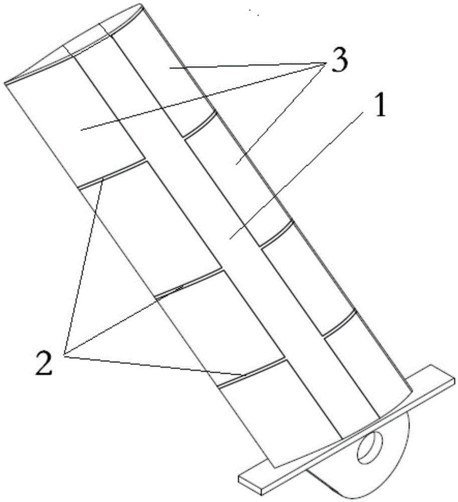
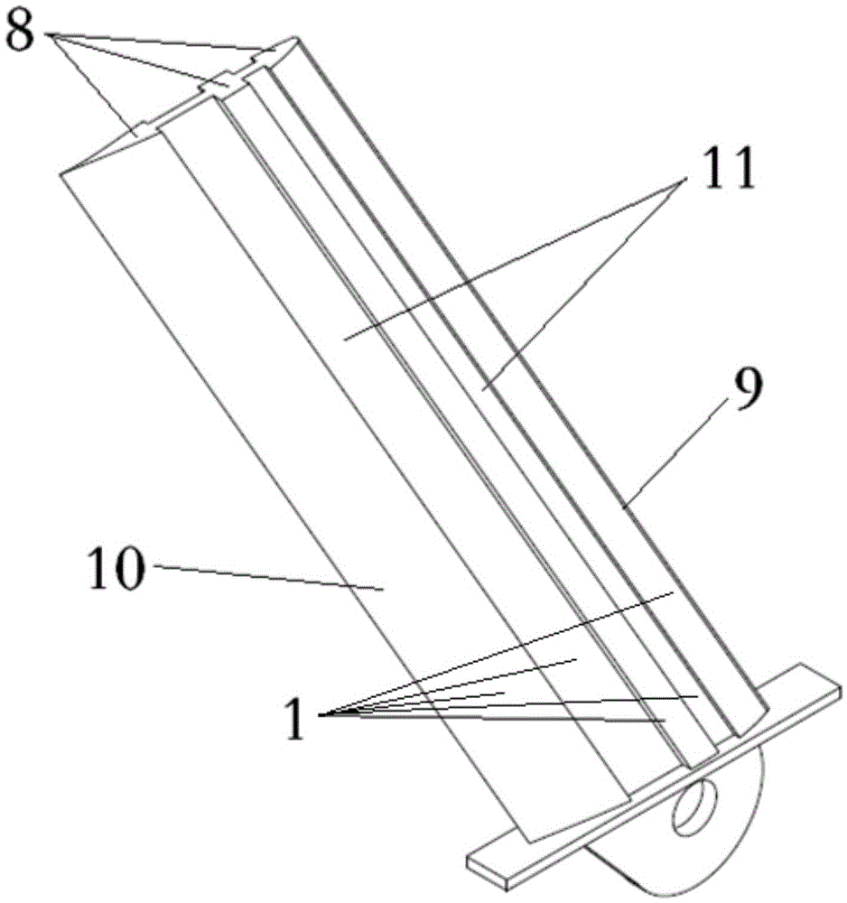
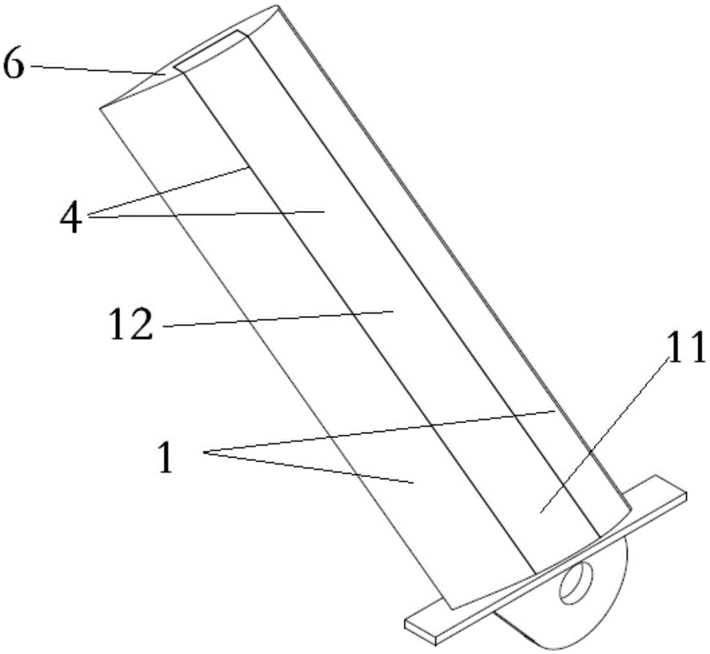
[0026] like figure 2 , image 3 As shown, the present invention includes metal girder 1 , rigid foam 12 and surface paint 4 .

[0027] First, the section stiffness required by the model will be calculated through the similarity relationship of the model design, and the model section design will be carried out by using the relevant 3D modeling software; the actual section stiffness of the model will be consistent with the required section stiffness of the model. The designed model section covers the leading edge 9 and the trailing edge 10 of the wing. Metal materials are then used to manufacture the model main beam 1, which includes the leading edge 9 and the trailing edge 10 of the airfoil. Then apply glue inside the groove 11 of the main beam, fill it with hard foam 12, and polish the edges of the foam to ensure that the shape of the model is consistent with the aerodynamic shape that the wing model should have. Finally, the surface of the foam 12 on the wing and the foam ...


PUM


Abstract

The invention provides a design method of a static aeroelasticity test model. The design method comprises the following steps: firstly, through a similarity relationship, calculating the section rigidity of the model, and utilizing relevant three-dimensional modeling software to carry out model section design, wherein the designed model section comprises the leading edge, the trailing edge and a windward side of a wing so as to realize a purpose on improving leading and trailing edge model rigidity; using rigid form to fill a metal girder so as to guarantee the aerodynamic configuration of the model; and painting the surface of the model to guarantee the surface flatness of the model. Through an integrative structural model, the deformation of the surface of the model in a wind tunnel test can be effectively reduced, and influence on wing aerodynamic force due to the deformation of the surface of the model is eliminated. In addition, since the leading edge and the trailing edge of the model are made of metal materials, the strength of the model is greatly improved.

Description

technical field [0001] The invention relates to wind tunnel test technology, in particular to static aeroelastic test technology, and belongs to the field of aerospace engineering. Background technique [0002] In order to measure the aeroelastic performance of the aircraft, the method of static air bomb test is usually used, and the static air bomb test technology is widely used in the field of aerospace engineering. [0003] like figure 1 As shown, the existing static aeroelastic test model includes: metal main girder 1, metal wing rib 2, outrigger beam, and lightweight filling material 3. The model usually uses a straight or nearly straight metal shaft as the main beam 1 of the model. The cross-sectional shape of the main beam 1 is usually a rectangular solid cross-section, and the section stiffness of the main beam will be equal to the section stiffness required by the model. In order to maintain the shape of the wing, corresponding outrigger beams 2 are added to the m...

Claims


Application Information

Patent Timeline
Patent Type & Authority Applications(China)
IPC IPC(8): G06F17/50
CPCG06F30/13Y02T90/00
Inventor 侯英昱吕计男刘子强陈农朱剑
Owner CHINA ACAD OF AEROSPACE AERODYNAMICS
Why Eureka
Try Eureka