Positioning aligner

A technology for calibrating devices and jaws, applied in electrical components, semiconductor/solid-state device manufacturing, circuits, etc., can solve the problems of wafer clamping, the efficiency of jaw Aligner structure needs to be improved, etc., to prevent slippage and reduce rotation. speed, the effect of improving the detection speed

Inactive Publication Date: 2016-06-08
SHENYANG SIASUN ROBOT & AUTOMATION
View PDF4 Cites 6 Cited by
  • Summary
  • Abstract
  • Description
  • Claims
  • Application Information

AI Technical Summary

Problems solved by technology

Since the detection of the bonding sheet does not require notch port alignment, the structural efficiency of the claw-type Aligner needs to be improved
[0007] At the same time, the existing claw-type Aligner also has a shortcoming: if Figure 4 As shown, when the eccentricity of the wafer 5' is too large, the wafer may only be supported by two brackets 2' during the process of placing the wafer by the manipulator. When the manipulator withdraws, the wafer will slide down. During the rising process, the wafer will be clamped by the bracket

Method used


Image

  • Positioning aligner
  • Positioning aligner
  • Positioning aligner

Examples


Embodiment Construction

[0037] In order to make the purpose, technical solution and advantages of the present invention more clear, the present invention will be further described in detail below in conjunction with the accompanying drawings and specific embodiments. It should be understood that the specific embodiments described here are only used to explain the present invention, but not to limit the present invention.

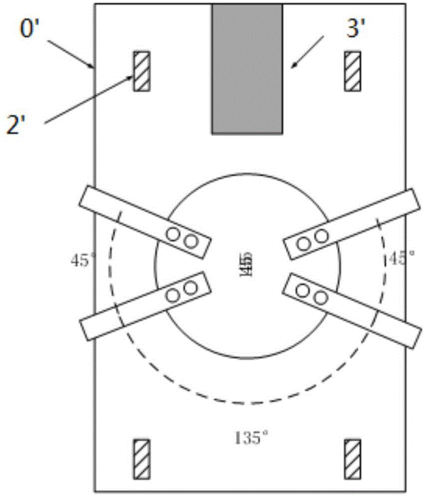
[0038] The positioning and calibration device of the present invention includes: a rotating shaft and four claws, the claws are arranged on the rotating shaft, the claws are arranged in turn around the rotation center of the rotating shaft, and the claws The included angles are 45 degrees, 135 degrees, 45 degrees, and 135 degrees; the direction of the included angle of 135 degrees forms a through space for the manipulator to transfer the wafer; the outer edge of the jaws surrounds and forms a circle whose radius is smaller than the radius of the wafer.

[0039] Such as Figure 5 A...


PUM


Abstract

The invention relates to the technical field of semiconductor manufacturing, and specifically discloses a positioning aligner. The positioning aligner comprises a rotating shaft and four claws. The claws are arranged on the rotating shaft, the claws are successively arranged to encircle the rotation center of the rotating shaft, and the angles formed between each two claws are respectively 45 degrees, 135 degrees, 45 degrees and 135 degrees; a through space is formed in the direction of the 135-degree included angles for transmitting a wafer by a manipulator; and the radius of a circle formed by encircling the external peripheries of claws is smaller than the radius of the wafer. According to the invention, the aligner for detecting eccentricity of a bonding pad by use of a claw structure, compared to a conventional claw type aligner, a carriage structure is cancelled, the rotating shaft does not have to ascend and descend, and an eccentricity detection function can be completed. At the same time, since an ascending and descending process is cancelled, the detection speed is greatly improved, and through properly reducing the rotation speed, wafer slip can be prevented.

Description

technical field [0001] The invention relates to the technical field of semiconductor manufacturing, in particular to a positioning calibration device with a novel jaw structure for supporting wafers. Background technique [0002] A positioning alignment device (also called an aligner, English Aligner) is a pre-alignment device used in wafer processing, and its main functions are eccentricity correction and notch alignment. In the workflow, the cooperating manipulator places the wafer on the Aligner, and the Aligner detects the degree of eccentricity of the wafer and the position of the notch, aligns the notch to the set angle, and informs the manipulator to take the wafer away. It is guaranteed that all wafers are in the same position during the next level of processing. [0003] At present, there are mainly two types of Aligner: adsorption type and claw type. The adsorption-type Aligner uses the principle of vacuum adsorption to fix the wafer, such as figure 1 As shown, ...

Claims


Application Information

Patent Timeline
Patent Type & Authority Applications(China)
IPC IPC(8): H01L21/68H01L21/66
Inventor 邹风山姜铁程刘晓帆李学威韩志平董状
Owner SHENYANG SIASUN ROBOT & AUTOMATION
Why Eureka
Try Eureka