
Multicoil switching wireless power transmission coupling device and control method thereof

A wireless power transmission and coupling device technology, applied in the direction of circuit devices, circuits, inductors, etc., can solve problems affecting system efficiency, large magnetic flux leakage, and increasing system complexity

Active Publication Date: 2016-06-08
XIANGTAN UNIV
View PDF3 Cites 7 Cited by
  • Summary
  • Abstract
  • Description
  • Claims
  • Application Information

AI Technical Summary

Problems solved by technology

However, the asymmetric coil structure will cause large magnetic flux leakage, which will affect the system efficiency; the relatively movable structure of the transmitting end and the receiving end needs to add additional position detection and transmission devices; the complex compensation network will increase the system efficiency. Complexity

Method used


Image

  • Multicoil switching wireless power transmission coupling device and control method thereof
  • Multicoil switching wireless power transmission coupling device and control method thereof
  • Multicoil switching wireless power transmission coupling device and control method thereof

Examples


Embodiment Construction

[0026] The present invention will be further described below in conjunction with the accompanying drawings and embodiments.

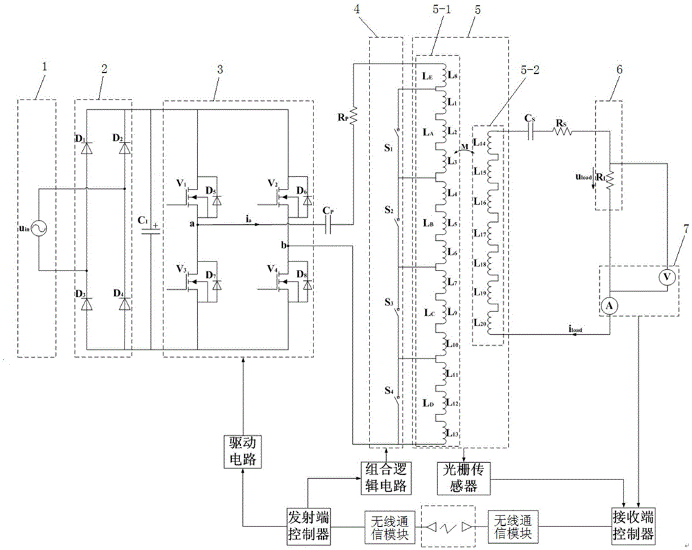
[0027] Such as figure 1 As shown, the present invention includes an AC voltage source 1, a rectifier 2, an inverter 3, a switch group 4, a coupler 5, a load 6, a grating sensor, a receiver controller, a transmitter controller, a combinational logic circuit, and a power detection module 7 and drive circuit, the rectifier 2 is a diode (D 1 -D 4 ) bridge rectifier, inverter 3 is a switching device (V 1 -V 4 ) with a reverse freewheeling diode (D 5 -D 8 ) of the full-bridge inverter.

[0028] The AC voltage source 1, the rectifier 2, the inverter 3, the coupler 5, and the load 6 are sequentially connected in series, the grating sensor is installed on the coupler 5, and the signal output end of the grating sensor is connected to the receiving end controller, and the receiving The controller at the transmitting end and the controller at the transmittin...


PUM


Abstract

The invention discloses a multicoil switching wireless power transmission coupling device. The multicoil switching wireless power transmission coupling device comprises an alternating-current voltage source, a rectifier, an inverter, a switch group, a coupler, a load, a grating sensor, a receiving end controller, a transmitting end controller and a combined logic circuit, wherein the alternating-current voltage source, the rectifier, the inverter, the coupler and the load are sequentially connected in series, the grating sensor is connected with the receiving end controller, the receiving end controller is connected with the transmitting end controller in a wireless communication mode, the transmitting end controller is connected with the combined logic circuit, the combined logic circuit is connected with the switch group, and the switch group is connected with the coupler. The transmitting end controller can accurately switch a working coil at the transmitting end of the coupler to a region over against the receiving end, accurately adjust the horizontal position diverge degree between the transmitting end and the receiving end of the coupler and control the conducting angle of a switch device in the inverter to accurately control output power of the inverter. The invention further discloses a control method of the multicoil switching wireless power transmission coupling device.

Description

technical field [0001] The invention relates to the field of wireless energy, in particular to a multi-coil switchable wireless energy transmission coupling device and a control method thereof. Background technique [0002] At present, in the inductive wireless power transfer system, in order to solve the problem that the current at the transmitting end of the system increases and the power at the receiving end decreases when there is a relative position deviation between the transmitting end and the receiving end of the coupler, the coupler is usually designed to be asymmetrical. Type structure, the relatively movable structure of the transmitting end and the receiving end, or an external compensation network. However, the asymmetric coil structure will cause large magnetic flux leakage, which will affect the system efficiency; the relatively movable structure of the transmitting end and the receiving end needs to add additional position detection and transmission devices; ...

Claims


Application Information

Patent Timeline
Patent Type & Authority Applications(China)
IPC IPC(8): H02J50/10H02J50/90H01F38/14
CPCH01F38/14H01F2038/146
Inventor 谭平安曹赛琪叶良伟
Owner XIANGTAN UNIV
Learn More