

Transverse flux permanent magnet motor
A permanent magnet motor, transverse magnetic flux technology, applied in the magnetic circuit static parts, magnetic circuit rotating parts, magnetic circuit shape/style/structure and other directions, can solve the problem of reducing the mechanical strength of the motor rotor structure and limiting the transverse magnetic flux Magnetic motor application, low space utilization and magnetic flux utilization, etc., to achieve the effect of reducing the risk of irreversible demagnetization, reducing rotor size and moment of inertia, and reducing rotor size
- Summary
- Abstract
- Description
- Claims
- Application Information
AI Technical Summary
Problems solved by technology
Method used
Image

Examples
Embodiment Construction
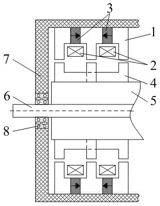
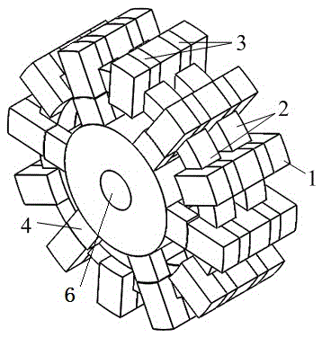
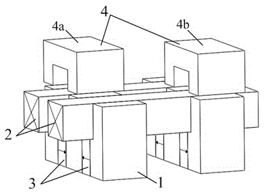
[0017] see figure 1 and figure 2 The motor structure of the present invention includes a stator core 1 , an armature winding 2 , a permanent magnet 3 , a rotor core 4 , a motor shaft 6 and a stator shell 7 made of non-magnetic material. Both the stator core 1 and the rotor core 4 are laminated with silicon steel sheets, and the material of the permanent magnet 3 is NdFeB with high coercive force. The outermost part is the non-magnetic material stator shell 7, the stator core 1 is fixedly connected to the inner wall of the non-magnetic material stator shell 7, and the non-magnetic material stator shell 7 is connected with the motor shaft 6 through the bearing 8. The stator core 1 is located outside the rotor core 4 , the stator core 1 is coaxial with the rotor core 4 , and there is a radial gap between the stator core 1 and the rotor core 4 . The rotor core 4 is coaxially fixedly sleeved outside the non-magnetic material rotor cylinder 5, and the non-magnetic material rotor ...
PUM
 Abstract
Description
Claims
Application Information