A space locking docking mechanism

A docking mechanism and space technology, which is applied to the docking device of aerospace vehicles and other directions, can solve the problems of many numbers and types, many unreliability factors, and large weight of the end grabbing system, and achieves improved reliability, simple structure, and high quantity. less effect

Active Publication Date: 2013-09-04
BEIJING INST OF SPACECRAFT SYST ENG
View PDF1 Cites 17 Cited by
  • Summary
  • Abstract
  • Description
  • Claims
  • Application Information

AI Technical Summary

Problems solved by technology

[0004] The above-mentioned locking mechanism mainly has the following problems: (1) The locking and electrical connection are realized by two sets of actuators, which brings repetition and complexity to the design of the mechanism, and the driving motor needs to pass through two different The spur gear train meets the needs of driving the locking and electrical connection mechanisms separately; (2) The locking and electrical connection of the end grabbing device are not synchronous and are driven by the same drive motor, which also affects the design of the mechanism and the transmission scheme of the mechanism. The design brings complexity, and the drive motor needs to be installed with a special clutch to meet the needs of the two mechanisms working at the same time; (3) The two independent mechanism transmission schemes of locking and electrical connection make the number and types of moving parts of the mechanism more, which means Not only the weight of the entire end grabbing system is relatively large, but also there are many unreliability factors

Method used


Image

  • A space locking docking mechanism
  • A space locking docking mechanism

Examples


Embodiment Construction

[0010] The present invention will be further described below in conjunction with accompanying drawing:

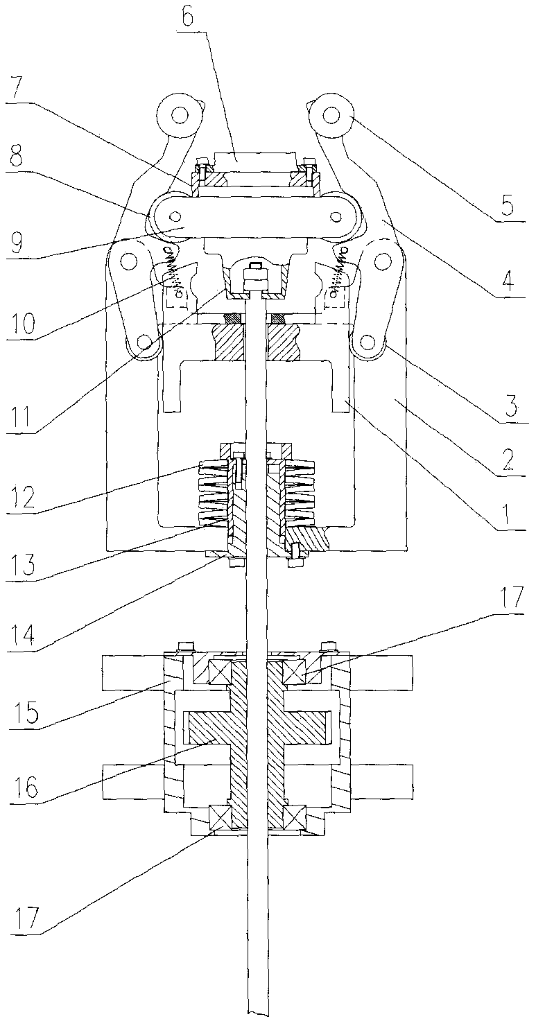
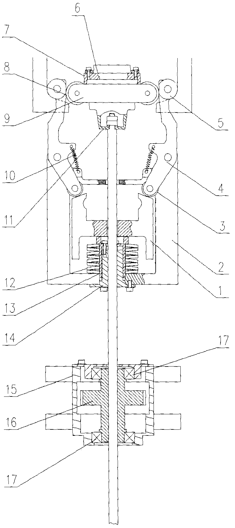
[0011] Such as figure 1 As shown, the present invention consists of a fixed bracket 1, a movable bracket 2, a locking link lower roller 3, a locking link 4, a locking link upper roller 5, an electrical connector 6, an electrical connector mounting seat 7, and a support frame Roller 8, support frame 9, receive spring 10, support frame base 11, disc spring 12, outer guide sleeve 13, inner guide sleeve 14, ball screw mount 15, ball screw 16 and bearing 17 constitute.

[0012] The side surface of the fixed bracket 1 adopts a cam design, and the cam surface is composed of a straight surface and an inclined surface. The movable bracket 2 is sleeved on the fixed bracket 1 and can move relative to the fixed bracket 1 . Two ">"-shaped locking links 4 are symmetrically hinged on both sides of the movable bracket 2, the hinge point is located at the center of the locking link 4, and ...


PUM


Abstract

A space locking docking mechanism, the movable bracket is set on the fixed bracket and can move relative to the fixed bracket, two ">" shaped locking links are symmetrically hinged on both sides of the movable bracket, and there are grooves on the inner surface of the locking links . The disc spring is installed at the bottom of the movable bracket, the nut of the ball screw is axially fixed, the screw of the ball screw passes through the movable bracket, the disc spring and the fixed bracket in sequence, and the end is connected with the support frame, and the support frame is supported on the locking connecting rod in the groove. The two ends of the receiving spring are respectively fixed on the movable bracket and the locking link to provide the restoring force when the locking link rotates relative to the movable bracket. When working, the nut of the ball screw rotates under the action of external force, and the screw driving the ball screw drives the support frame, locking connecting rod, and movable support to move together. After moving to a certain distance, the disc spring is compressed by the fixed support, and the support frame Slip out from the inner surface groove of the locking link and slide along the inner surface of the locking link, and spread the upper end of the locking link to achieve locking of the target.

Description

technical field [0001] The invention relates to a locking device for space target capture. Background technique [0002] The space manipulator is an indispensable tool for humans to engage in space activities on the space station. For example, the capture and docking of large-scale space station cabins, the assembly and maintenance of instruments and equipment, and the operation of assisting astronauts, etc., all require the cooperation of the space manipulator to perform well. [0003] The end-grabbing technology of the space manipulator is one of the key technologies of the space manipulator, and the end-grabbing device of the space manipulator is a key component of the space manipulator. The patent application number is US4929011, and the US patent named "GRAPPLEFIXTURE" discloses a structure of a grasping device at the end of a space manipulator, which is mainly composed of a capture and docking device, a locking mechanism, an electrical connection mechanism, and a drive...

Claims


Application Information

Patent Timeline
Patent Type & Authority Patents(China)
IPC IPC(8): B64G1/64
Inventor 李新立张文明孙国鹏王耀兵胡成威
Owner BEIJING INST OF SPACECRAFT SYST ENG
Why Eureka
Try Eureka