Ultrasonic probe and ultrasonic detection method

An ultrasonic detection and ultrasonic probe technology, applied in the field of medical devices, can solve the problems of multi-storage space, occupation, and increase in the cost of medical devices.

Active Publication Date: 2018-09-28
VINNO TECH (SUZHOU) CO LTD
View PDF7 Cites 0 Cited by
  • Summary
  • Abstract
  • Description
  • Claims
  • Application Information

AI Technical Summary

Problems solved by technology

This will lead to frequent replacement of ultrasound probes by doctors, increase the workload of doctors, and increase the cost of medical equipment, and there are too many types of ultrasound probes, which is inconvenient to manage
For example, a variety of ultrasound probes take up a lot of storage space, and the ultrasound machine needs to have more ultrasound probe interfaces that are convenient for doctors to replace, and places for temporary placement of ultrasound probes

Method used


Image

  • Ultrasonic probe and ultrasonic detection method
  • Ultrasonic probe and ultrasonic detection method
  • Ultrasonic probe and ultrasonic detection method

Examples


Embodiment 1

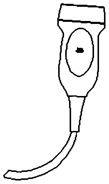
[0027] figure 2 This is a schematic structural diagram of an ultrasonic probe provided in Embodiment 1 of the present invention. This embodiment is applicable to medical ultrasonic testing. The ultrasonic probe specifically includes: a casing 10, a probe connecting wire 11, a probe transducer 12, and a lens changer 13 , and matching layer 14 .

[0028] The probe connecting line 11 is arranged at one end of the housing 10, and is used to transmit the ultrasonic detection signal of the designated part sent by the ultrasonic detection system to the probe transducer 12, and transmit the electrical signal returned by the probe transducer 12 to the probe transducer 12. Ultrasonic detection system; the probe transducer 12, which can include a piezoelectric unit, is arranged in the housing 10 and connected to the probe connecting line 11, and is used to generate ultrasonic waves according to the ultrasonic detection signals of the designated parts, and to receive the reflected ultras...

Embodiment 2

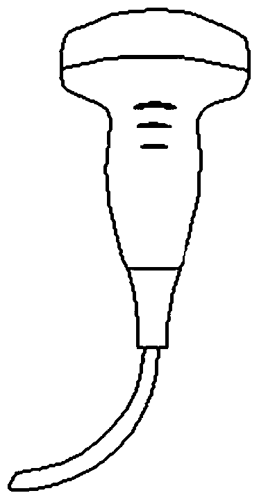
[0034] Figure 5 This is a schematic structural diagram of a probe transducer provided in the second embodiment. On the basis of the first embodiment, this embodiment provides the preferred structure of the probe transducer, that is, the probe transducer is provided with a plurality of piezoelectric The unit and the switch that controls the on and off of the piezoelectric unit are used to generate ultrasonic waves with different fixed center frequencies. The probe transducer of the ultrasonic probe includes: a first piezoelectric unit 20, a first switch 21 and a first element matching controller 22.

[0035] Among them, the first piezoelectric unit 20 is used to generate ultrasonic waves with a fixed center frequency when the power is turned on, and at the same time receive the reflected ultrasonic waves, and the number of the first piezoelectric units 20 is at least two, which are stacked; The wires are connected with the first piezoelectric units 20 in one-to-one correspond...

Embodiment 3

[0040] Image 6 It is a schematic structural diagram of a probe transducer provided in the third embodiment. On the basis of the first embodiment, the third embodiment provides another realization structure of the probe transducer. In the piezoelectric unit of the probe transducer A filter is added to obtain ultrasonic waves with a fixed center frequency associated with a designated part to be inspected from the reflected ultrasonic waves. The transducer of the ultrasonic probe specifically includes: a second piezoelectric unit 30, a second switch 31 and The second element matches the controller 32 .

[0041] Among them, the second piezoelectric unit 30 is used to generate multi-frequency ultrasonic waves when the power is turned on, and at the same time filter the reflected ultrasonic waves to obtain the ultrasonic waves of the fixed center frequency; the second switch 31 is connected to the second The piezoelectric unit 30 is connected to control the power-on and power-off ...


PUM


Abstract

An embodiment of the invention discloses an ultrasonic probe and an ultrasonic testing method. The ultrasonic probe comprises a casing, a probe connection wire, a probe transducer, a lens converter and a matching layer, wherein the lens converter comprises a rectangular lens and a lens shape conversion control part and is arranged at the other end of the casing and connected with the matching layer, the lens shape conversion control part is used for changing the shape of the rectangular lens to be matched with a pointed part, and at least one of a linear array probe lens, an arc array probe lens and a phased array probe lens is realized. According to the ultrasonic probe and the ultrasonic testing method, ultrasonic testing of different depth to the skin and different parts of a human body is realized.

Description

technical field [0001] Embodiments of the present invention relate to the field of medical devices, and in particular, to an ultrasonic probe and an ultrasonic detection method. Background technique [0002] The ultrasound system radiates the ultrasound signal generated from the transducer of the ultrasound probe to the inside of the target object, and receives information of the echo signal reflected from the inside of the target object, thereby acquiring an image of the inside of the target object. Specifically, ultrasound systems are used in medicine to look inside the human body, detect foreign objects, and assess damage. [0003] Ultrasound systems have higher stability than diagnostic equipment using X-rays, display images in real time, and are safe because there is no exposure to radioactive substances, so they are widely used together with other medical image diagnostic equipment. [0004] In the prior art, since each organ of the body has different distances from t...

Claims


Application Information

Patent Timeline
Patent Type & Authority Patents(China)
IPC IPC(8): A61B8/00
CPCA61B8/4444A61B8/4455
Inventor 白银章
Owner VINNO TECH (SUZHOU) CO LTD
Why Eureka
Try Eureka