
High-safety bone drilling device for department of orthopaedics

A safe and orthopedic technology, applied in the field of medical devices, can solve the problems of increasing surgical risk, aggravating patient pain, and increasing patient pain, so as to reduce the risk of surgery, ensure physical safety, and reduce labor intensity.

Active Publication Date: 2016-06-15
东平东原技术开发有限公司
View PDF12 Cites 10 Cited by
  • Summary
  • Abstract
  • Description
  • Claims
  • Application Information

AI Technical Summary

Problems solved by technology

[0002] In clinical medicine, fracture is a common bone trauma disease, and the most common way to treat fractures is to implement internal fixation surgery, that is, to connect the bones with bone plates and steel nails. After healing, the bone nails need to be removed. Bone drills are often needed. Bone drills are a commonly used medical device. The treatment process of patients is an extremely important process. The performance of various medical devices in the treatment also determines whether the patient's treatment effect is good or bad. The traditional bone drill has the defects of cumbersome use and poor flexibility, and cannot better meet the various necessity requirements of medical staff in the treatment process. Every time drilling or taking nails, it is necessary to move the patient's limbs, which is very difficult to use. Inconvenient, this not only increases the difficulty of the doctor's work, but also increases the pain of the patient, because the bone drill generates vibration when drilling the bone, so the doctor is very unstable when holding the bone drill to drill the bone, which increases the pain of the patient and increases the pain of the patient. Risks of Major Surgery

Method used


Image

  • High-safety bone drilling device for department of orthopaedics

Examples


Embodiment Construction

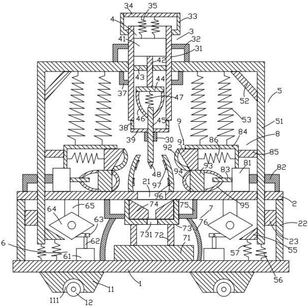
[0017] Such as figure 1 As shown, the orthopedic bone drilling device with high safety of the present invention includes a base plate 1, a support plate 2 located above the base plate 1, a frame device 3 located above the support plate 2, and a frame device 3 arranged on the frame device 3. The motor device 4 inside, the bracket device 5 located on the left and right sides of the frame device 3, the cylinder device 6 located above the bottom plate 1, the friction device 7 located below the motor device 4, the support plate 2 located The pushing device 8 on the left and right sides above and the fixing device 9 arranged on the pushing device 8 .

[0018] Such as figure 1 As shown, the bottom plate 1 is in the shape of a cuboid, and the bottom plate 1 is placed horizontally. The bottom plate 1 is provided with a first support block 11 below it and a first roller 12 below the first support block 11 . The first support block 11 is provided with two and is respectively located on...


PUM


Abstract

A high-safety bone drilling device for the department of orthopaedics comprises a bottom plate, a supporting plate, a frame device, a motor device, support devices, air cylinder devices, a friction device, pushing devices and fixing devices. The bottom plate is provided with first supporting blocks and first rolling wheels. The supporting plate is provided with a first square hole, first supporting rods and first connecting blocks. The frame device comprises a frame, first supports, second supports, a first cross rod, first springs, third supports, first connecting rods, a first positioning plate and a positioning ring. The motor device comprises a first motor, a first rotating shaft, a second cross rod, a positioning rod, first bent rods, a second spring, a second rotating shaft and a drill bit. Each support device comprises a moving rack, a first inclined rod, third springs, a triangular block, a fourth spring and a fifth spring. Each air cylinder device comprises an air cylinder, a pushing rod, a second connecting rod, a rotating block and a second supporting rod. Each friction device comprises a cushion block and third supporting rods. The high-safety bone drilling device for the department of orthopaedics can be used for drilling the bone of a patient stably and relieves the labor intensity of a doctor.

Description

technical field [0001] The invention relates to the technical field of medical devices, in particular to a highly safe orthopedic bone drilling device. Background technique [0002] In clinical medicine, fracture is a common bone trauma disease, and the most common way to treat fractures is to implement internal fixation surgery, that is, to connect the bones with bone plates and steel nails. After healing, the bone nails need to be removed. Bone drills are often needed. Bone drills are a commonly used medical device. The treatment process of patients is an extremely important process. The performance of various medical devices in the treatment also determines whether the patient's treatment effect is good or bad. The traditional bone drill has the defects of cumbersome use and poor flexibility, and cannot better meet the various necessity requirements of medical staff in the treatment process. Every time drilling or taking nails, it is necessary to move the patient's limbs,...

Claims


Application Information

Patent Timeline
IPC IPC(8): A61B17/16
CPCA61B17/16
Inventor 刘湘静
Owner 东平东原技术开发有限公司
Learn More