Practical stirring device

A stirring device and practical technology, which are applied to mixers with rotary stirring devices, accessories of mixers, transportation and packaging, etc., can solve the problems of low probability of mutual contact, complicated temperature control methods, and inability to understand the degree in real time, and achieve heating Convenience, simple structure, and the effect of improving the stirring effect

Inactive Publication Date: 2016-06-15
XUZHOU BEIER ELECTRIC CO LTD
View PDF0 Cites 2 Cited by
  • Summary
  • Abstract
  • Description
  • Claims
  • Application Information

AI Technical Summary

Problems solved by technology

When the internal raw materials are reacting, on the one hand, the degree of progress cannot be known in real time; on the other hand, the full progress of the reaction depends to a large extent on the uniformity of mutual mixing, and the existing reactor usually uses a motor to drive the stirring shaft Continuous rotation in a certain direction for a certain period of time, the reactants basically flow together as a whole, the probability of contact with each other is small and the time is short, it is not easy to stir evenly, and consumes a lot of energy; in addition, some reactions need to be kept at a fixed temperature can only be carried out, and the current temperature control method is more complicated and the effect is not good

Method used


Image

  • Practical stirring device

Examples


Embodiment Construction

[0010] The present invention will be described in further detail below in conjunction with the accompanying drawings.

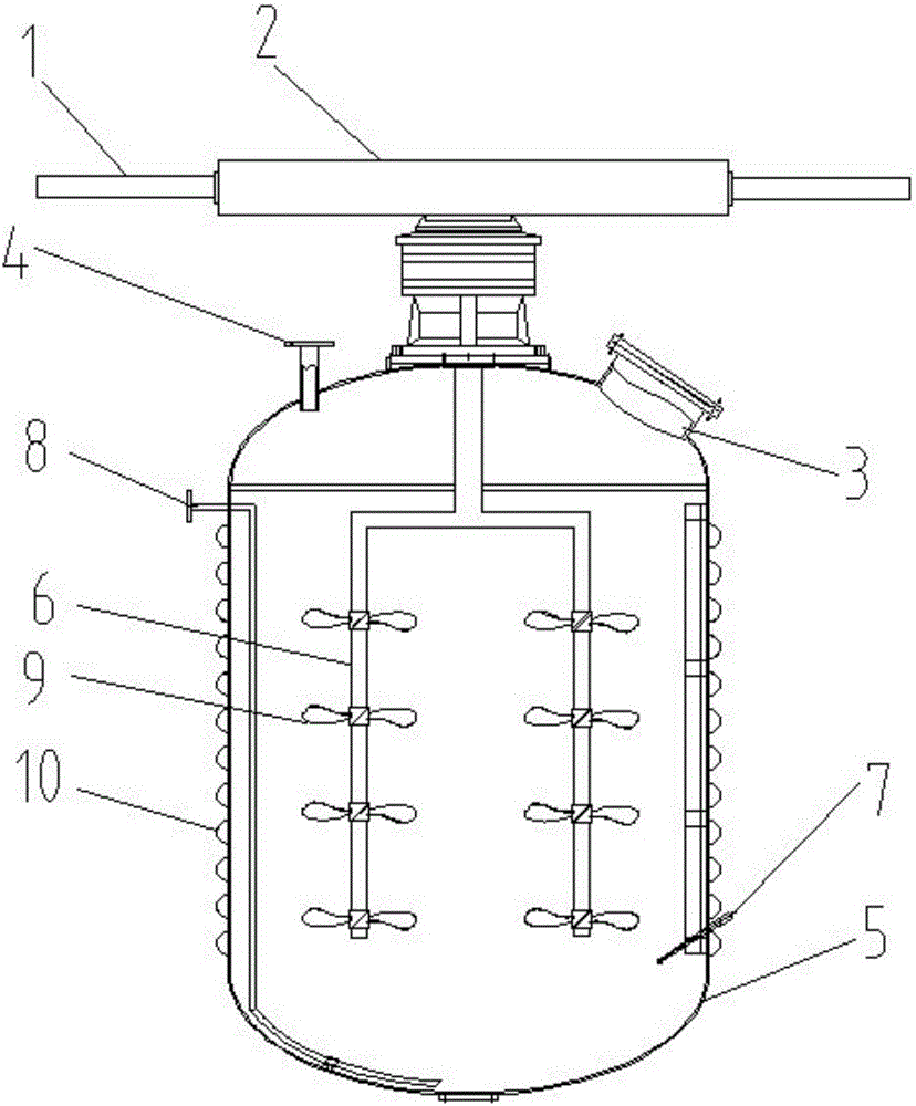
[0011] Such as figure 1 A practical stirring device shown includes a tank body 5 and a stirring shaft body. The stirring shaft body penetrates into the tank body 5 vertically from the top of the tank body 5. The stirring shaft body is driven to rotate by a driving device, and is evenly and densely covered on the tank body 5. An electric heating ring 10 is installed, and a plurality of detection probes 7 are installed from the side of the tank body 5, and the detection probes 7 penetrate into the tank body 5; the lower end of the stirring shaft body is divided into two symmetrical stirring shafts 6, and 4 A stirring impeller 9, the driving device includes a rack case 2, and one end of the stirring shaft body upper end extending out of the tank body 5 is connected with the rack in the rack case 2 through a gear, and the two ends of the rack are respectively con...


PUM


Abstract

The invention discloses a practical stirring device. Electric heating rings are uniformly and densely arranged on a tank body in a sleeving way; a plurality of detecting probes are arranged on the side face of the tank body and extend into the tank body; the lower end of a stirring shaft body is divided into two symmetric stirring shafts; four stirring impellers are uniformly arranged on each stirring shaft; a driving device comprises a rack box; one end, extending out of the tank body, of the upper end of the stirring shaft body, is connected with a rack in the rack box through a gear; each of two ends of the rack is connected with an oil cylinder. According to the practical stirring device disclosed by the invention, the structure is simple, relevant parameters of materials can be detected in real time, and the progress of reaction can be known in real time; by setting a reciprocated stirring mode and arranging the two stirring shafts, mutual contact time of different materials is shortened, the speed of a chemical reaction and the stirring effect can be improved, and the production efficiency is improved; the stirring shafts are driven by the oil cylinders and the gear box to rotate, and an electric motor is omitted, so that energy consumption is low; by arranging the electric heating rings, the heating is realized more conveniently.

Description

technical field [0001] The invention relates to a stirring device, in particular to a practical stirring device. Background technique [0002] Stirring is often required in the production process of some physical or chemical products, and at the same time, the products are synthesized by physical or chemical reactions under certain temperature and pressure. When the internal raw materials are reacting, on the one hand, the degree of progress cannot be known in real time; on the other hand, the full progress of the reaction depends to a large extent on the uniformity of mutual mixing, and the existing reactor usually uses a motor to drive the stirring shaft Continuous rotation in a certain direction for a certain period of time, the reactants basically flow together as a whole, the probability of contact with each other is small and the time is short, it is not easy to stir evenly, and consumes a lot of energy; in addition, some reactions need to be kept at a fixed temperatur...

Claims


Application Information

Patent Timeline
Patent Type & Authority Applications(China)
IPC IPC(8): B01J19/18B01F7/22B01F15/00B01F27/91
CPCB01J19/0066B01J19/18B01J2219/00135B01F27/074B01F27/212B01F27/191B01F27/91B01F35/3231
Inventor 周淑淑
Owner XUZHOU BEIER ELECTRIC CO LTD
Why Eureka
Try Eureka