
Loading tank shifting and transporting device

A technology for transfer devices and loading tanks, which is applied in the directions of transportation and packaging, loading/unloading, conveyors, etc., and can solve problems such as overload sensitivity, excessive loading, foreign matter jamming, etc.

Active Publication Date: 2016-06-15
CHNA ENERGY INVESTMENT CORP LTD +1
View PDF5 Cites 4 Cited by
  • Summary
  • Abstract
  • Description
  • Claims
  • Application Information

AI Technical Summary

Problems solved by technology

[0003] 1) Temperature limitation: The temperature of conveying materials is generally around 60°C, and the cast chain hoist with the best temperature resistance can only be used for conveying lumpy and powdery materials whose temperature does not exceed 300°C. If the temperature is too high, it will cause safety problems. Doubts, for high-temperature solid materials at 300°C-1000°C, neither the material nor the structure can meet the high-temperature requirements;
[0004] 2) The sealing performance is poor. General lifting devices can meet the sealing requirements of solid materials, but during the transportation of high-temperature materials, flammable or toxic gases may be produced, so the original lifting devices cannot meet the requirements of the system. Gas tightness requirements;
[0005] 3) The safety and stability are relatively poor. Most of the original lifting equipment is sensitive to overload, and it is prone to excessive loading or foreign matter jamming during the transportation process, and the safety requirements for flammable or toxic gases are often not involved;
[0006] 4) The loading member and traction member of the lifting equipment are easy to wear

Method used


Image

  • Loading tank shifting and transporting device
  • Loading tank shifting and transporting device
  • Loading tank shifting and transporting device

Examples


Embodiment 1

[0147] Embodiment 1: In the pyrolysis reaction system of the solid heat carrier coal graded refining of a set of coal handling capacity 3000 tons / day, adopted the above-mentioned material airtight conveying system of the present invention for its solid heat carrier (hot semi-coke) ) delivery. The high-temperature solid material in this example is hot semi-coke, the temperature of the material is 600°C, the particle size of the material is 6-25mm, the outer diameter of the tank is 1.7m, the height is 2.2m, the effective volume is 1.3m3, and the loading capacity is 600kg each time. , Combined with the weight of the equipment, the total weight is about 7 tons, that is, the weight of each transportation and lifting is about 7 tons. The loading tank with hot materials can be moved horizontally and lifted / lowered by hoisting and transferring tooling, realizing the cycle of hot semi-coke.

[0148] During operation, when the airtight transportation of high-temperature solid materials...


PUM

PropertyMeasurementUnit
Lengthaaaaaaaaaa

Abstract

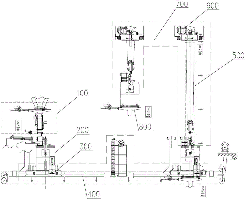
The invention discloses a loading tank shifting and transporting device. The loading tank shifting and transporting device comprises a loading tank (200), a bottom layer shifting and transporting guide track (400) and a bottom layer travelling crane (300), wherein a tank body unloading opening (212) is formed in the bottom wall of a tank body (210) of the loading tank; a self-weight sealing valve is mounted on the tank body unloading opening; a loading tank supporting part (311) and a loading tank unloading part (312) which are used for positioning and supporting the tank body are arranged on a crane body (310) of the bottom layer travelling crane; the loading tank supporting part can support the self-weight sealing valve to block the tank body unloading opening; and an unloading through hole (313) is formed in the loading tank unloading part, therefore, when the tank body is supported on the loading tank unloading part, the tank body unloading opening is aligned with the unloading through hole, and the self-weight sealing valve can open the tank body unloading opening under the self-weight effect or under the effect of gravity of materials in the tank body. The loading tank shifting and transporting device is compact in structure and reasonable in layout and line arrangement, and can adapt to various working conditions of transporting, loading and unloading.

Description

technical field [0001] The invention belongs to the field of conveying equipment, and in particular relates to a closed conveying system for high-temperature materials in the field of coal chemical industry, and a pyrolysis reaction system using the conveying system. Background technique [0002] In industrial production, there are many types of continuous conveying equipment (such as lifting devices) for conveying powdery, granular and small block materials vertically or at a large inclination angle, such as belt conveyors, chain conveyors, bucket elevators, Scraper conveyor, etc. Various lifting devices are suitable for various fields according to their respective characteristics, but generally have the following characteristics: [0003] 1) Temperature limitation: The temperature of conveying materials is generally around 60°C, and the cast chain hoist with the best temperature resistance can only be used for conveying lumpy and powdery materials whose temperature does n...

Claims


Application Information

Patent Timeline
IPC IPC(8): B65G35/00B65G65/32B65G65/40
CPCB65G35/00B65G65/32B65G65/40B65G2201/04
Inventor 麻林郭治曾鸣王勤张峰苌亮李君李晓峰赵香龙秦强刘书贤龙灏
Owner CHNA ENERGY INVESTMENT CORP LTD
Learn More