Novel hoisting device

A hoisting device, a new type of technology, applied in the direction of switchgear, electrical components, cranes, etc., can solve the problems of low efficiency, high personnel and equipment, and achieve the effect of improving efficiency, low equipment cost, and reliable installation

Inactive Publication Date: 2016-06-15
GUIZHOU POWER GRID CO LTD ZUNYI POWER SUPPLY BUREAU
View PDF4 Cites 3 Cited by
  • Summary
  • Abstract
  • Description
  • Claims
  • Application Information

AI Technical Summary

Problems solved by technology

However, there are many shortcomings in this working mode, which is inefficient and has high risks to personnel and equipment.

Method used


Image

  • Novel hoisting device
  • Novel hoisting device

Examples


Embodiment Construction

[0023] The invention will be further introduced below in conjunction with the accompanying drawings and specific embodiments.

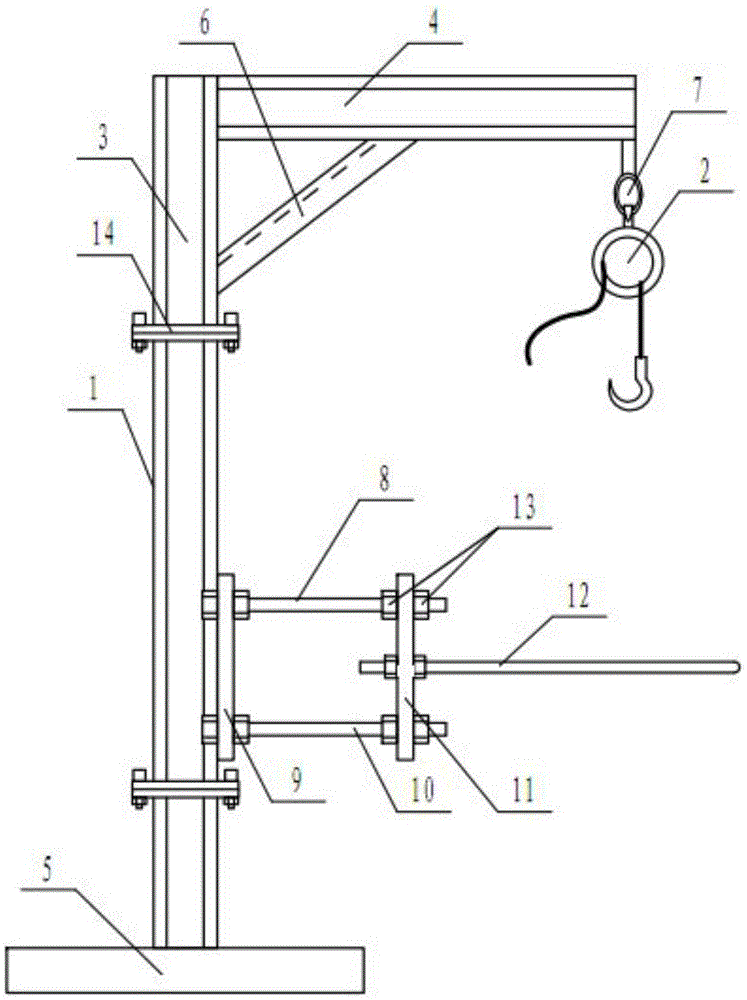
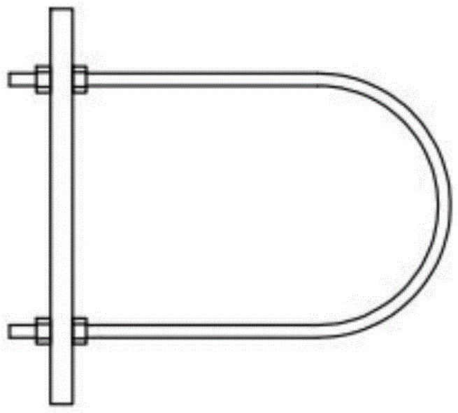
[0024] Such as Figure 1 ~ Figure 2 As shown, a novel hoisting device includes a support frame 1 and a chain block 2. The support frame 1 includes a column 3 and a horizontal cantilever 4 fixedly connected to the top of the column 3. The lower end of the free end of the cantilever 4 is hung with a As for the chain hoist 2, the bottom end of the column 3 is provided with a support plate 5.

[0025] Preferably, the column 3 and the cantilever 4 are made of I-shaped steel material respectively, and the notch is oriented perpendicular to the plane formed by the column 3 and the cantilever 4. The I-shaped steel is easy to purchase and cut, and has a high tensile strength, which can meet the on-site load-bearing capacity .

[0026] Preferably, the above-mentioned cantilever 4 and column 3 joints are provided with an inclined reinforcing rib 6, one end of ...


PUM


Abstract

The invention discloses a novel hoisting device which comprises a supporting frame and a chain block. The supporting frame comprises a stand column and a horizontal cantilever fixedly connected to the top end of the stand column. The chain block is connected to the lower end of the free end of the cantilever in a hung mode. The bottom end of the stand column is provided with a supporting plate. By the adoption of the supporting frame and the chain block, the number of workers is greatly reduced; the working efficiency is greatly improved; more time and labor are saved; the construction period is completed on schedule; the power failure interval is shortened, the operation reliability of a power grid is guaranteed, and the position is adjusted easily; and the novel hoisting device is compact in structure, capable of being used in a narrow space and convenient to use and operate and also has the characteristics that equipment is simple in structure and low in cost.

Description

technical field [0001] The invention relates to a novel hoisting device, which belongs to the technical field of electric power maintenance equipment. Background technique [0002] Limited by the location of the site, when replacing electrical equipment in some special locations (near the wall of the substation, indoor high-voltage room), due to the narrow space, the crane cannot reach it, which increases the difficulty of on-site operations. Similar situations are manually pushed and pulled. , lifting, etc., to replace the device to the designated location. However, purely manual work is risky, and a little carelessness will cause damage to personnel and equipment. Moreover, such a work mode requires a large number of personnel to participate, and the construction period cannot be guaranteed, and the situation of extending the power outage time is often encountered. Moreover, it is difficult to fine-tune the position after the equipment is put in place by manpower replacem...

Claims


Application Information

Patent Timeline
IPC IPC(8): B66C23/16H02B3/00
CPCB66C23/166H02B3/00
Inventor 郑平李锦李肃张道秋潘航罗智燃甘毅王永洪赵岩罗金龙
Owner GUIZHOU POWER GRID CO LTD ZUNYI POWER SUPPLY BUREAU
Why Eureka
Try Eureka