Supercharge Your Innovation With Domain-Expert AI Agents!

Variable valve timing device

A valve timing and variable technology, used in valve devices, engine components, machines/engines, etc., can solve the problems of high cost, difficult processing, low efficiency, etc., and achieve low processing costs, easy finished products, and wear-resistant Effect

Inactive Publication Date: 2016-06-15
JIANGSU HAILONG ELECTRICAL APPLIANCE
View PDF0 Cites 2 Cited by
  • Summary
  • Abstract
  • Description
  • Claims
  • Application Information

AI Technical Summary

Problems solved by technology

There will be a slight sound during the opening and closing of the locking device, and the cavity formed by the outer cover 2 and the gear insert 1 has an acoustic effect, which amplifies the sound, especially when the engine is idling; In addition, the outer cover 2 is made of aluminum alloy, and the internal cavity needs to be processed as a whole, which is difficult to process, high in cost, and low in efficiency

Method used


Image

  • Variable valve timing device
  • Variable valve timing device
  • Variable valve timing device

Examples


Embodiment 1

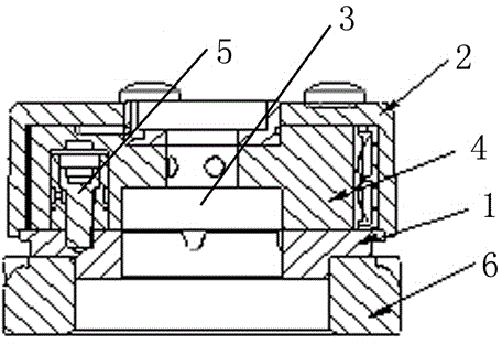
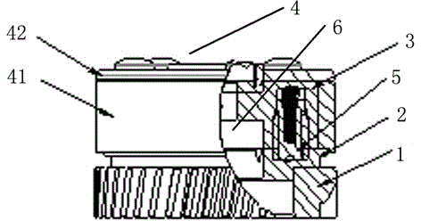
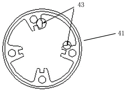
[0024] Such as Figure 2 to Figure 5 As shown, a variable valve timing device of the present invention includes a helical gear 1, a gear insert 2, a rotor 3 and an outer cover 4. The helical gear 1 is connected with the outer cover 4 through a gear insert 2, and the gear insert 2 and the outer cover 4. A hydraulic chamber is formed. In the hydraulic chamber, there is a rotor 3 connected to the gear insert 2 through a locking device 5. The middle part of the rotor 3 is connected to the camshaft 6. The locking device 5 includes a locking pin 51 and a locking pin hole 52. The locking pin 51 is placed on the lower surface of the rotor 3 , the upper surface of the gear insert 2 is provided with a locking pin hole 52 matching the locking pin 51 , and the bottom of the locking pin 51 is provided with an oil storage tank 53 . There is an oil storage tank 53 at the bottom of the locking pin 51, and a certain amount of lubricating oil is retained in the oil storage tank 53 of the lockin...


PUM


Abstract

The invention relates to a variable valve timing device. The variable valve timing device comprises a helical gear, a gear insert, a rotor and an outer cover. The helical gear is connected with the outer cover through the gear insert; a hydraulic chamber is formed through the gear insert and the outer cover; the rotor which is connected with the gear insert through a locking device is disposed in the hydraulic chamber; the middle of the rotor is connected with a cam shaft; the locking device comprises a locking pin and a locking pin hole; the locking pin is disposed on the lower surface of the rotor; the locking pin hole matched with the locking pin is formed in the upper surface of the gear insert; and an oil storing groove is formed in the bottom of the locking pin. The variable valve timing device has the advantages that the oil storing groove is formed in the bottom of the locking pin, so that a certain amount of lubricating oil is reserved in the oil storing groove of the locking pin after halt, abnormal sound produced during starting after halt for a long time is reduced, meanwhile the contact area is decreased, and the friction force is reduced.

Description

technical field [0001] The invention relates to a variable valve timing device for adjusting the phase angle of a camshaft. Background technique [0002] There is an existing helical gear variable valve timing device, the transmission part is a helical gear, which is a kind of component of the helical gear meshing mode. exist figure 1 Among them, the gear 6 is connected with the outer cover 2 through the gear insert 1 to form a hydraulic chamber, and the rotor 4 connected with the camshaft 3 is built in, and the rotor is driven by the hydraulic medium to make the phase change of the camshaft 3 relative to the crankshaft, and the circulation of the medium Realized by electromagnetic hydraulic valve. The existing design uses a pressure medium to open the locking device 5 on the rotor 4 and the gear insert 1, so that the timing is advanced. Then, the locking pin of the rotor 4 falls into the pin hole of the sprocket wheel through the reverse pressure medium to form a locked ...

Claims


Application Information

Patent Timeline
Patent Type & Authority Applications(China)
IPC IPC(8): F01L1/344
Inventor 朱圣明张宪
Owner JIANGSU HAILONG ELECTRICAL APPLIANCE
Features
  • R&D
  • Intellectual Property
  • Life Sciences
  • Materials
  • Tech Scout
  • Unparalleled Data Quality
  • Higher Quality Content
  • 60% Fewer Hallucinations
Learn More