Direct current brushed motor speed measurement device and speed measurement method

A technology of DC brushed motor and speed measuring device, which is applied in the direction of devices using electric/magnetic methods, and can solve problems such as increasing costs

Inactive Publication Date: 2016-06-15
JIANGSU REYA ELECTRIC
View PDF6 Cites 17 Cited by
  • Summary
  • Abstract
  • Description
  • Claims
  • Application Information

AI Technical Summary

Problems solved by technology

At present, the speed detection of brushed motors mainly uses methods such as tachogenerators, photoelectric encoders, and Hall sensors. These methods usually require additional equipment on the motor, which not only greatly increases the cost, but also affects the use of There are still higher requirements for the environment and the mechanical structure of the motor

Method used


Image

  • Direct current brushed motor speed measurement device and speed measurement method
  • Direct current brushed motor speed measurement device and speed measurement method
  • Direct current brushed motor speed measurement device and speed measurement method

Examples


Embodiment 1

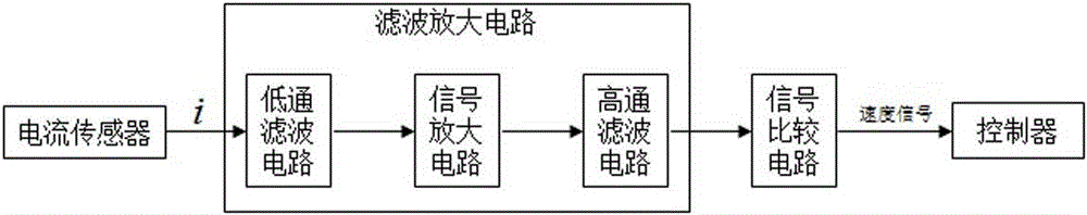
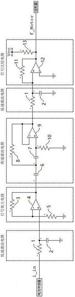
[0038] Such as figure 1 and figure 2 As shown, the DC brush motor speed measuring device of the present invention includes a current sensor, a filter amplifier circuit, a signal comparison circuit and a controller, and the current sensor, filter amplifier circuit, signal comparison circuit and controller are sequentially connected in series. The controller has a built-in logical operation unit.

[0039] The filtering and amplifying circuit includes a low-pass filtering circuit, a signal amplifying circuit and a high-pass filtering circuit.

[0040] The low-pass filter circuit includes a first resistor 1, the input end of the first resistor 1 is the input end of the low-pass filter circuit, and the output end of the first resistor 1 is the output end of the low-pass filter circuit , and the output terminal of the first resistor 1 is grounded through a first capacitor 2 .

[0041] The signal amplifying circuit includes a first operational amplifier 4, the positive input of t...

Embodiment 2

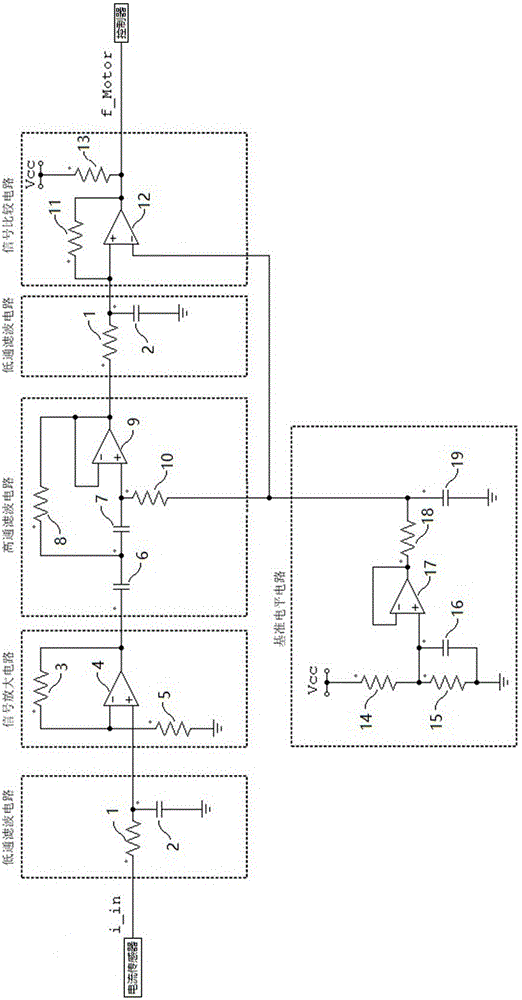
[0050] Such as figure 1 and image 3 As shown, the DC brush motor speed measuring device of the present invention includes a current sensor, a filter amplifier circuit, a signal comparison circuit and a controller, and the current sensor, filter amplifier circuit, signal comparison circuit and controller are sequentially connected in series. The controller has a built-in logical operation unit.

[0051] The filtering and amplifying circuit includes a low-pass filtering circuit, a signal amplifying circuit and a high-pass filtering circuit.

[0052] The low-pass filter circuit includes a first resistor 1, the input end of the first resistor 1 is the input end of the low-pass filter circuit, and the output end of the first resistor 1 is the output end of the low-pass filter circuit , and the output terminal of the first resistor 1 is grounded through a first capacitor 2 .

[0053] The signal amplifying circuit includes a first operational amplifier 4, the positive input of th...


PUM


Abstract

The invention relates to a direct current brushed motor speed measurement device and speed measurement method. The speed measurement device is characterized by comprising a current sensor, a filter amplifying circuit, a signal comparison circuit, and a controller which are serially connected in turn. A logical operation unit is arranged in the controller. The speed measurement method is characterized by comprising the steps of: collecting a current signal of the direction current brushed motor through the current sensor; filtering and removing high frequency noise and direct current component in the current signal through the filter amplifying circuit; amplifying the signal; comparing a pulse component of the current signal with a reference voltage through the signal comparison circuit; generating a high-low alternating square wave speed signal to the controller; finally calculating the period or frequency of the speed signal through a logical operation unit built in the controller; and combining the number of mica sheets in a direct current brushed motor commutator and obtaining the corresponding motor speed through simple calculation. The speed measurement device and the speed measurement method can realize the speed measurement function of the direct current brushed motor through a simple circuit combination without increasing additional large devices on the motor, have low cost and no limitation of the use environment or a motor mechanical structure, and have a more accurate measurement result.

Description

technical field [0001] The invention relates to a test device, in particular to a device and method for measuring the speed of the commutator (ie, the rotor) of a DC brushed motor. Background technique [0002] DC brushed motors are widely used in industrial and civil industries. In order to control the speed of DC brushed motor, it is necessary to detect the rotational speed of the motor first, and then control it. At present, the speed detection of brushed motors mainly uses methods such as tachogenerators, photoelectric encoders, and Hall sensors. These methods usually require additional equipment on the motor, which not only greatly increases the cost, but also affects the use. There are also higher requirements for the environment and the mechanical structure of the motor. Contents of the invention [0003] The problem to be solved by the present invention is to provide a DC brushed motor speed measuring device, which can realize the speed measuring function through...

Claims


Application Information

Patent Timeline
Patent Type & Authority Applications(China)
IPC IPC(8): G01P3/48
CPCG01P3/48
Inventor 季欣杰孔小明戴政
Owner JIANGSU REYA ELECTRIC
Why Eureka
Try Eureka