Carbon fiber reinforced composite material unidirectional laminate two-dimensional cutting force modeling method

A technology for reinforced composite materials and unidirectional laminates, applied in the field of mechanical cutting, can solve the problems of fiber orientation limitation, lack of quantitative guidance, and no public reports of CFRP two-dimensional cutting force modeling methods, reaching high levels. Prediction accuracy, the effect of realistic guidance

Inactive Publication Date: 2016-06-15
SHANGHAI JIAO TONG UNIV
View PDF2 Cites 14 Cited by
  • Summary
  • Abstract
  • Description
  • Claims
  • Application Information

AI Technical Summary

Problems solved by technology

Although this kind of theoretical model explains the mechanical behavior of CFRP unidirectional laminates during cutting from the material removal mechanism to a certain extent, it is limited by the fact that the shear slip is obviously not suitable for the reverse fiber direction angle. There are restrictions on the direction of the fibers
In addition, in order to expand the applicability of the model in unidirectional long fiber reinforced materials, this kind of theoretical model is generally only based on the me

Method used


Image

  • Carbon fiber reinforced composite material unidirectional laminate two-dimensional cutting force modeling method
  • Carbon fiber reinforced composite material unidirectional laminate two-dimensional cutting force modeling method
  • Carbon fiber reinforced composite material unidirectional laminate two-dimensional cutting force modeling method

Examples


Embodiment

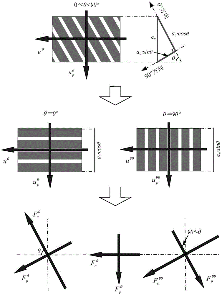
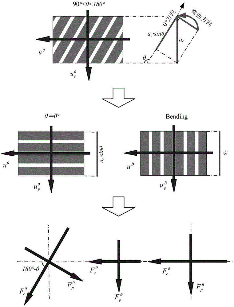
[0057] In this embodiment, a diamond-coated cemented carbide flying knife (rake angle γ 0 = 25°, relief angle α = 15°, cutting edge blunt circle radius r ε =15μm), workpiece material (T700CFRP unidirectional laminate), cutting thickness a c =20um, cutting speed V c = 100, 150, 200, 250, 300, fiber direction angle θ = 0,90 (parallel, vertical), 15,30,45,60,75 (along fiber), 105,120,135,150,165 (reverse fiber) as experimental parameters; cutting force The collection is done by Kistler-9272 force measuring instrument.

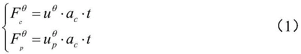
[0058] The modeling method of two-dimensional cutting force of carbon fiber reinforced composite unidirectional laminate specifically includes the following steps:

[0059] In the first step, the same tool parameters (γ 0 =25°,α=15°,r ε =15μm, diamond coating), the same cutting parameters (V c =200m / min,a c =20μm) to carry out right-angle free cutting experiments of T700CFRP single-layer plywood under different fiber direction angles θ=15, 30, 45, 60, 75 (f...


PUM


Abstract

The invention discloses a carbon fiber reinforced composite material unidirectional laminate two-dimensional cutting force modeling method.A cutting force model under any fiber direction angle can be obtained according to a directionality cutting ratio so that the two-dimensional cutting force model can predict two-dimensional cutting force under different fiber direction angles.The method comprises the following steps that fiber direction angles theta are 0 degree, 90 degrees and 135 degrees respectively for performing carbon fiber reinforced composite material unidirectional laminate two-dimensional cutting experiments to obtain basic data for modeling; according to the basic data obtained through the cutting experiments when the theta is 0 degree and 90 degrees, a two-dimensional cutting force model of the carbon fiber reinforced composite material unidirectional laminate under any direction angle along fiber is built; according to the basic data obtained by the cutting experiments when the theta is 0 degree and 135 degrees, a two-dimensional cutting force model of the carbon fiber reinforced composite material unidirectional laminate under any direction angle opposite to fiber is built.According to the carbon fiber reinforced composite material unidirectional laminate two-dimensional cutting force modeling method, influences of a cutting mechanism and anisotropism are considered, the prediction precision of the obtained two-dimensional cutting force model is higher, and the method can be used for designing and manufacturing a cutting tool for carbon fiber reinforced materials and determining cutting technological paths and parameters.

Description

technical field [0001] The present invention relates to the cutting process of carbon fiber reinforced composite material unidirectional laminated plate, and specifically relates to a modeling method of two-dimensional cutting force of carbon fiber reinforced composite material unidirectional laminated plate based on directional cutting specific energy, which belongs to mechanical cutting field of processing technology. Background technique [0002] The typical two-dimensional cutting force modeling of metal materials is mainly based on the assumption of shear slip. It is believed that there is a shear slip surface in the cutting process of metal materials, and the shear slip surface After the workpiece material reaches the shear stress limit, it slips along the shear angle and forms the final chip. The more classic calculation formulas for the shear angle during orthogonal cutting of metal materials include the M.E. Merchant model and the Lee and Shaffer model. Carbon Fib...

Claims


Application Information

Patent Timeline
IPC IPC(8): G06F17/50
CPCG06F30/17G06F30/367G06F2119/18
Inventor 陈明文亮明伟伟安庆龙蔡晓江
Owner SHANGHAI JIAO TONG UNIV
Why Eureka
Try Eureka