Two-dimensional electronic scanning antenna

A scanning antenna, two-dimensional electronic technology, applied in the fields of communication, measurement and control, can solve problems such as complex structure, achieve the effect of low equipment complexity, low power consumption, and improve antenna gain

Inactive Publication Date: 2016-06-15
SPACE STAR TECH CO LTD
View PDF3 Cites 12 Cited by
  • Summary
  • Abstract
  • Description
  • Claims
  • Application Information

AI Technical Summary

Problems solved by technology

The invention discloses a two-dimensional electronic scanning antenna, which overcomes the shortcomings of the existing two-dimensional electronic scanning antenna with complex structure, and simplifies the components of the antenna.

Method used


Image

  • Two-dimensional electronic scanning antenna
  • Two-dimensional electronic scanning antenna
  • Two-dimensional electronic scanning antenna

Examples


no. 1 example 12

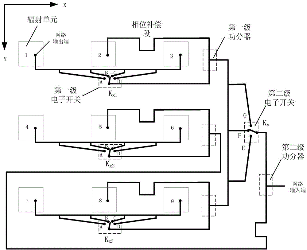
[0021] figure 1 It is a schematic diagram of a 12-beam 3×3 array antenna in the first embodiment of the present invention;

[0022] refer to figure 1 , the antenna device in the embodiment of the present invention includes an antenna array composed of 9 radiating elements. The 9 radiating units are divided into three groups, that is, 3 radiating unit groups, and according to figure 1 Arranged in the manner shown, thus forming a two-dimensional antenna array.

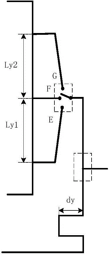
[0023] At the same time, the antenna device also includes a two-dimensional feeding network with a single-port input and nine-port output connected to the two-dimensional antenna array. The two-dimensional feeding network can be divided into a first transmission line and a second transmission line, thereby forming Secondary feed network.

[0024] Divided into 3 groups of radiating single-ended, using a 3×3 rectangular grid arrangement, for one group of radiating unit groups can be identified by figure 1 It consists ...


PUM


Abstract

The invention discloses a two-dimensional electronic scanning antenna. The two-dimensional electronic scanning antenna comprises a two-dimensional antenna array and also comprises first transmission lines, wherein the two-dimensional antenna array comprises at least two radiation unit groups, each radiation unit group at least comprises two radiation units, the first transmission lines are in correspondence to the radiation units, and each first transition line is connected with the two radiation units in one of the radiation unit groups and is used for simultaneously adjusting the phases of the two radiation units. By the two-dimensional electronic scanning antenna, the defect of structural complexity of a traditional two-dimensional electronic scanning antenna is overcome, and a constituent component of the antenna is simplified.

Description

technical field [0001] The invention belongs to antenna technology in the fields of measurement, control and communication, and relates to a two-dimensional electronic scanning antenna, in particular to a two-dimensional electronic scanning antenna based on a radio frequency switch. Background technique [0002] For an antenna with a fixed beam, there is a contradiction between antenna gain and beam coverage. Generally speaking, the higher the antenna gain, the smaller the angular range covered by the antenna beam. Therefore, in order to solve the above-mentioned contradiction, two methods are usually adopted: one is to install the antenna on the servo device, and realize the mechanical scanning of the antenna beam by the rotation of the servo mechanism, but the servo mechanism greatly increases the volume and weight of the antenna, and The scanning speed of the antenna beam is restricted by the servo mechanism; another way is to use the phased array antenna to realize the ...

Claims


Application Information

Patent Timeline
Patent Type & Authority Applications(China)
IPC IPC(8): H01Q3/08
Inventor 王国龙董涛尹建勇韩琳刘亚奇
Owner SPACE STAR TECH CO LTD
Why Eureka
Try Eureka