Unattended monitoring cabinet

A technology of monitoring cabinets and monitoring hosts, which is applied in substation/distribution device shells, etc., which can solve problems such as messy distribution of components and display components, cumbersome opening and opening process of cabinet doors, and unreasonable installation structure of components, etc., to achieve openness Closing is convenient and reliable, saves space, and has the effect of reasonable layout

Inactive Publication Date: 2016-06-15
XIAN GALAXY POWER INTELLIGENT ELECTRIC
View PDF0 Cites 0 Cited by
  • Summary
  • Abstract
  • Description
  • Claims
  • Application Information

AI Technical Summary

Problems solved by technology

[0002] Users who have long been committed to the monitoring system design of unattended power supply stations have found that traditional power distribution cabinets cannot meet our needs. Specifically, the door opening and opening process of traditional iron sheet monitoring cabinets or power distribution cabinets is too cumbersome At the same time, the installation structure of traditional components is unreasonable, and the distribution of components and display parts is too messy, which is easy to cause wiring and electromagnetic interference; the temperature sensor installed in the existing cabinet needs Connect the power cord, the more temperature sensors there are, the greater the impact on the wiring harness layout inside the cabinet

Method used


Image

  • Unattended monitoring cabinet
  • Unattended monitoring cabinet
  • Unattended monitoring cabinet

Examples


Embodiment Construction

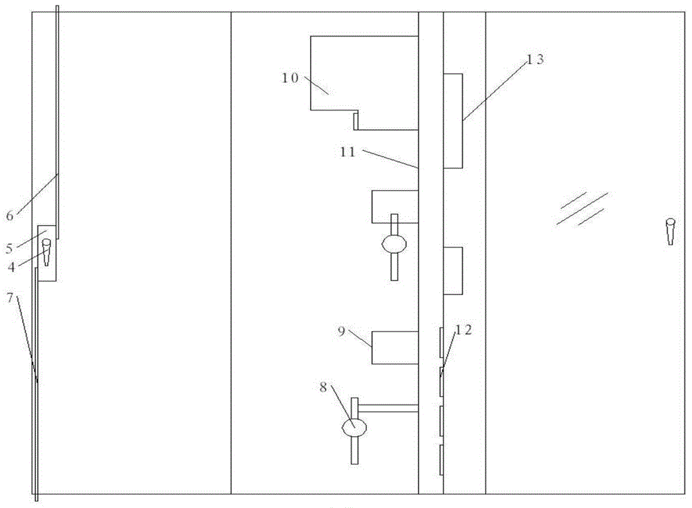
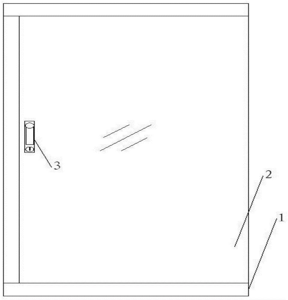
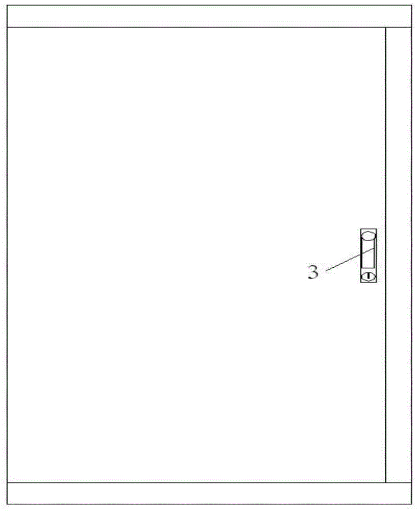
[0020] like figure 1 , figure 2 and image 3 The shown unattended monitoring cabinet includes a cabinet body 1 and a cabinet door 2 installed on the cabinet body 1, and the cabinet door 2 includes a front cabinet door and a back cabinet door respectively arranged on the front and back of the cabinet body 1 , the front cabinet door is a transparent door, the back cabinet door is an iron door, a front lock 3 is installed on the front cabinet door, a back lock 4 is installed on the back cabinet door, and the front lock 3 includes a key Holes and rotating handles, the back lock 4 includes a lock hook that rotates coaxially with the rotating handle of the front lock 3, the back lock 4 is provided with a double-ended lock 5, and the upper and lower sides of the double-ended lock 5 An upper locking rod 6 and a lower locking rod 7 are respectively connected, and the lock hook rotates to drive the upper locking rod 6 and the lower locking rod 7 to move toward or back; the inside of ...


PUM


Abstract

The invention discloses an unattended monitoring cabinet. The unattended monitoring cabinet comprises a cabinet body and a cabinet door mounted on the cabinet body, wherein the cabinet door comprises a front surface cabinet door and a back surface cabinet door mounted on the front surface and the back surface of the cabinet body respectively; a front surface lock is mounted on the front surface cabinet door; a back surface lock is mounted on the back surface cabinet door; the front surface lock comprises a key hole and a rotary handle; the back surface lock comprises a lock hook; the back surface lock is equipped with a dual-head lockset; an upper locking rod and a lower locking are connected with the upward side and the downward side of the dual-head lockset respectively; the lock hook rotationally drives the upper locking rod and the lower locking rod to move relatively or in opposite; a mounting partition plate is arranged in the cabinet body; a monitor and an inserting-connecting assembly are mounted on one side, facing to the front surface cabinet body, of the mounting partition plate; an electric appliance mounting frame, a monitoring host computer and a passive wireless temperature sensor are mounted on one side, facing to the back surface cabinet body, of the mounting partition plate. The cabinet door of the unattended monitoring cabinet is reasonable in structure, and convenient and reliable to open and close; the components and parts in the cabinet body are reasonably arranged; and in addition, the temperature sensor adopts the wireless passive structure, so that sable and reliable operation of the unattended monitoring cabinet can be realized.

Description

technical field [0001] The invention belongs to the technical field of monitoring cabinet equipment, and in particular relates to an unattended monitoring cabinet. Background technique [0002] Users who have long been committed to the monitoring system design of unattended power supply stations have found that traditional power distribution cabinets cannot meet our needs. Specifically, the door opening and opening process of traditional iron sheet monitoring cabinets or power distribution cabinets is too cumbersome At the same time, the installation structure of traditional components is unreasonable, and the distribution of components and display components is too messy, which is likely to cause wiring and electromagnetic interference; the temperature sensor installed in the existing cabinet needs When the power cord is connected, the more temperature sensors there are, the greater the impact on the wiring harness layout inside the cabinet. Contents of the invention [...

Claims


Application Information

Patent Timeline
Patent Type & Authority Applications(China)
IPC IPC(8): H02B1/26
Inventor 汪奎卫荣平
Owner XIAN GALAXY POWER INTELLIGENT ELECTRIC
Why Eureka
Try Eureka