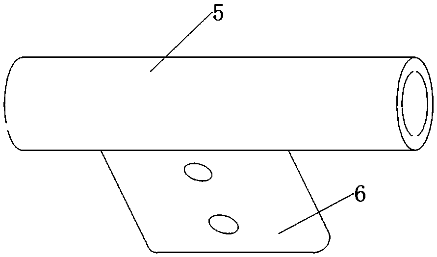
A strain clamp for composite core reinforced cable

A tension clamp, composite core technology, applied in textile cables, cable installation, cable suspension devices, etc., can solve the problems affecting the promotion of composite core reinforced cables, high installation process requirements, harsh construction requirements, etc. Widely used, good diversion effect, and the effect of reducing labor intensity

Active Publication Date: 2018-03-02
帕尔普线路器材有限公司 +1
View PDF8 Cites 0 Cited by
  • Summary
  • Abstract
  • Description
  • Claims
  • Application Information

AI Technical Summary

Problems solved by technology

[0003] However, at present, the traditional compression type and bolt type clamps in the power industry cannot effectively hold this kind of wire. The existing special wedge-shaped composite core strengthened cable connection and tension clamps have high manufacturing costs and high installation process requirements. Harsh, seriously affecting the promotion of composite core reinforced cables

Method used


Image

  • A strain clamp for composite core reinforced cable
  • A strain clamp for composite core reinforced cable
  • A strain clamp for composite core reinforced cable

Examples


Embodiment Construction

[0027] The present invention will now be described more fully with reference to the accompanying drawings, in which exemplary embodiments of the invention are shown. This invention may, however, be embodied in many different forms and should not be construed as limited to the exemplary embodiments set forth herein. Rather, these embodiments are provided so that this disclosure will be thorough and complete, and will fully convey the scope of the invention to those skilled in the art.

[0028] For ease of description, spatially relative terms such as "upper," "lower," "left," and "right" may be used herein to describe the relationship of one element or feature relative to another element or feature shown in the figures. It will be understood that the spatial terms are intended to encompass different orientations of the device in use or operation in addition to the orientation depicted in the figures. For example, if the device in the figures is turned over, elements described ...


PUM


Abstract

The invention discloses a strain-resistant clamp for a composite core reinforced cable. The strain-resistant clamp includes a tension layer, a flow-guiding aluminum sleeve and a carbon core protective cap; wherein, the carbon core protective cap is set on the exposed composite core end ;The tension layer is wound on the outer surface of the exposed composite core at the connection end of the composite core strengthened cable; a part of the guide aluminum sleeve is set on the outside of the tension layer, and the other part is set on the outside of the aluminum conductor at the connection end of the composite core strengthened cable; , first strip the conductor at the connection end of the composite core reinforced cable to a set length, set the carbon core protective cap on the exposed composite core end, then wrap the tension layer on the exposed composite core outer surface, and finally place the conductive aluminum sleeve The tube sleeve is set at the connection between the end of the tension layer and the unstripped conductor end, and is crimped to connect the tension layer with the conductor of the outer layer of the cable. The strain clamp of the present application has a simple structure and is convenient for installation and maintenance.

Description

technical field [0001] The invention relates to a strain-resistant clamp for connecting, fixing and tensioning an overhead power transmission and distribution line to a composite core reinforced cable. Background technique [0002] The mechanical part of the composite core reinforced cable is made of a single composite mandrel or multi-strand composite mandrel, which has a very low thermal expansion rate, high strength, light weight, strong corrosion resistance, Non-magnetic, strong flexibility, high elasticity and other characteristics, for the erection of new lines due to light weight and small sag, it has the advantages of reducing the height of the iron tower and widening the span between the iron towers, thereby reducing the cost of the iron tower. The coefficient is low, it can withstand high temperature and short-term overload, and the arc sag can also be guaranteed at a safe height. The replacement of the wire has the advantages of reducing the load of the iron towe...

Claims


Application Information

Patent Timeline
Patent Type & Authority Patents(China)
IPC IPC(8): H02G7/02
CPCH02G7/02H02G7/05F16G11/06H02G7/056
Inventor 马跃吴文吉孙霄伟谢清辉
Owner 帕尔普线路器材有限公司
Why Eureka
Try Eureka