
Horizontal and vertical type hydraulic regulating motor regulator

A technology for adjusting motors and regulators, which is applied in the direction of electrical components, electromechanical devices, and electric components. It can solve the problems of time-consuming and laborious replacement of motor installation belts and affect the normal production of oil fields, etc., and achieve fast and convenient motor installation and debugging. Ergonomic effect

Inactive Publication Date: 2016-06-15
黄骅市天华石油机械有限公司
View PDF5 Cites 2 Cited by
  • Summary
  • Abstract
  • Description
  • Claims
  • Application Information

AI Technical Summary

Problems solved by technology

[0003] The invention provides a horizontal and vertical hydraulic adjustment motor regulator to solve the problem in the prior art that the installation of the motor and the replacement of the belt take time and effort and affect the normal production of the oilfield

Method used


Image

  • Horizontal and vertical type hydraulic regulating motor regulator
  • Horizontal and vertical type hydraulic regulating motor regulator
  • Horizontal and vertical type hydraulic regulating motor regulator

Examples


example 1

[0014] Example 1 Horizontal Motor Regulator

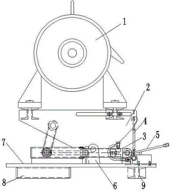
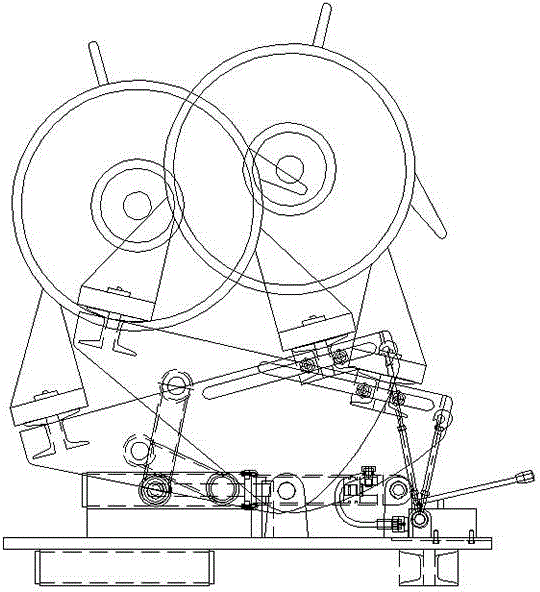
[0015] Such as figure 1 and figure 2 As shown, a motor regulator is mainly composed of a frame plate 2, a motor fixed base, a base plate 7 and a hydraulic rotation adjustment mechanism. The motor 1 is placed on the motor fixed base, and the motor fixed base is installed on the frame plate 2. The frame plate 2 The two sides are respectively connected to the bottom plate 7 through support ears 6. The hydraulic rotation adjustment mechanism includes a hydraulic cylinder 3 and an oil volume control valve 5. The oil volume control valve 5 is connected to the hydraulic cylinder 3. The hydraulic cylinder 3 is horizontally arranged at the bottom of the frame plate 2. The top end of the piston rod of the hydraulic cylinder 3 is connected to the front end of the frame plate 2, and a locking device 4 is provided between the other end of the frame plate 2 and the bottom plate 7. The longitudinal channel steel 8 and the transverse channel ste...

example 2

[0016] Example 2 Vertical Motor Regulator

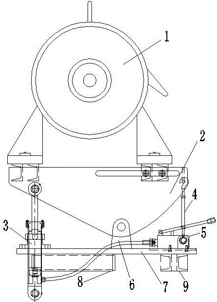
[0017] Such as image 3 and Figure 4 As shown, a motor regulator is mainly composed of a frame plate 2, a motor fixed base, a base plate 7 and a hydraulic rotation adjustment mechanism. The motor 1 is placed on the motor fixed base, and the motor fixed base is installed on the frame plate 2. The frame plate 2 The two sides are respectively connected to the bottom plate 7 through support ears 6. The hydraulic rotation adjustment mechanism includes a hydraulic cylinder 3 and an oil volume control valve 5. The oil volume control valve 5 is connected to the hydraulic cylinder 3. The hydraulic cylinder 3 is vertically arranged at the bottom of the frame plate 2. , the top end of the piston rod of the hydraulic cylinder 3 is connected to the front end of the frame plate 2, a locking device 4 is provided between the other end of the frame plate 2 and the bottom plate 7, and the longitudinal channel steel 8 and the transverse channel steel...


PUM


Abstract

The horizontal and vertical hydraulic adjustment motor adjuster is mainly composed of a frame plate, a motor fixing base, a base plate and a hydraulic rotation adjustment mechanism. The adjusting mechanism includes a hydraulic oil cylinder and an oil quantity control valve. The oil quantity control valve is connected with the hydraulic oil cylinder. The hydraulic oil cylinder is arranged at the bottom of the frame plate. The top end of the piston rod of the hydraulic oil cylinder is connected with the front end of the frame plate. Locking device. The hydraulic rotary adjustment mechanism of the present invention has a reasonable design, is safe and reliable, is convenient and light, and has a unique self-locking device, which enables it to be self-locked after debugging, is safe and stable, and can quickly and conveniently perform motor installation and belt replacement during use. Operation, especially in the belt replacement operation, can greatly save time, reduce labor costs, increase work efficiency, and improve oil well production.

Description

technical field [0001] The invention relates to the technical field of oilfield exploitation equipment, in particular to a horizontal and vertical hydraulically adjustable motor regulator for convenient installation of motors and belt replacement of pumping units in oilfield exploitation. Background technique [0002] The pumping unit is a kind of machinery and equipment for extracting oil, which makes the oil come out of the well by means of pressurization. The pumping unit is mainly composed of a beam-connecting rod-crank mechanism, a motor and auxiliary equipment. At present, the motor base of the pumping unit is a fixed structure. The belt is replaced, and the replacement process of the belt needs to move the motor, which requires the cooperation of multiple workers, which is time-consuming and laborious, greatly increasing the labor cost, low work efficiency, and affecting the normal production of the oil well. Contents of the invention [0003] The invention provide...

Claims


Application Information

Patent Timeline
Patent Type & Authority Applications(China)
IPC IPC(8): H02K5/26
CPCH02K5/26
Inventor 王秀军周小东沈高健高乐刘海军申超姚国杰孙凤余谢明东王忠
Owner 黄骅市天华石油机械有限公司
Learn More