
Image stabilizing method and compound image stabilizing system based on mechanical image stabilizing and electronic image stabilizing

An electronic image stabilization and image stabilization technology, which is applied to the parts of TV systems, parts of color TVs, TVs, etc., can solve the problems that the degree of image shift between frames cannot be too large, the working environment of the imaging system is complicated, and the cost is high , to avoid complex calculations, reduce impact, and improve real-time performance

Inactive Publication Date: 2016-06-15
NANTONG UNIVERSITY
View PDF2 Cites 22 Cited by
  • Summary
  • Abstract
  • Description
  • Claims
  • Application Information

AI Technical Summary

Problems solved by technology

However, electronic image stabilization uses digital image processing technology to determine the inter-frame offset of the image sequence and perform reverse compensation to generate a stable image sequence. Compared with mechanical image stabilization and optical image stabilization, it has the advantages of low cost and strong flexibility, but it is also There is a limit that the degree of image shift between frames cannot be too large
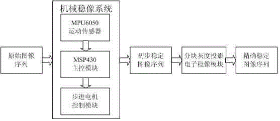
[0004] The working environment of the imaging system based on the mobile platform is complicated, and it often needs to stabilize the field of view at a large deflection angle. It is difficult to meet the demand with electronic image stabilization technology alone. If the high-precision mechanical image stabilization technology is used, the cost is too high. Therefore, a new method is proposed. A composite image stabilization system, which uses MEMS sensors and stepping motors to form a mechanical image stabilization system to achieve preliminary stabilization of the camera platform, and then uses electronic image stabilization technology to obtain high-quality stable image sequences

Method used


Image

  • Image stabilizing method and compound image stabilizing system based on mechanical image stabilizing and electronic image stabilizing
  • Image stabilizing method and compound image stabilizing system based on mechanical image stabilizing and electronic image stabilizing
  • Image stabilizing method and compound image stabilizing system based on mechanical image stabilizing and electronic image stabilizing

Examples


Embodiment Construction

[0049] Depend on figure 1 It can be seen that a composite image stabilization system based on mechanical image stabilization and electronic image stabilization includes MPU6050 motion sensor module, MSP430 main control module, stepping motor control module and electronic image stabilization module, wherein the motion sensor module and the main control The modules are connected, and the main control module is connected with the motor control module to realize the preliminary stabilization of the image sequence, and the result is used as the input of the electronic image stabilization module.

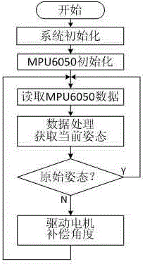
[0050] A composite image stabilization system based on mechanical image stabilization and electronic image stabilization. The motion sensor module uses a 6-axis motion sensor MPU6050, the main control module uses an MSP430 single-chip microcomputer, and the motor angle compensation module uses a 2-phase 4-wire stepping motor. The MPU6050 integrates a 3-axis MEMS gyroscope and a 3-axis MEM...


PUM


Abstract

The invention discloses an image stabilizing method and a compound image stabilizing system based on mechanical image stabilizing and electronic image stabilizing. A mechanical image stabilizing system based on an MPU6050 motion sensor and a stepping motor is employed to control the deflection angle of a camera within five DEG; and then, an electronic image stabilizing method based on block gray-level projection is employed to perform global motion estimation through a median filtering method, so as to remove interframe small amplitude high frequency jitter, thereby realizing accurate image stabilizing. The system comprises an MPU6050 sensor module, an MSP430 master control module, a motor control module and an electronic image stabilizing module. The compound image stabilizing system can adapt to camera wide-angle deflection and complex environments and meet the requirements of a motion platform imaging system.

Description

technical field [0001] The invention relates to an image stabilization method and an image stabilization system based on mechanical image stabilization and electronic image stabilization. Background technique [0002] A stable image sequence is not only convenient for manual observation and recognition, but also a necessary prerequisite for follow-up processing such as tracking and compression encoding. Due to many interference factors in the working environment of the camera platform, such as the camera shake caused by the movement of the mobile platform itself or external interference, the obtained video sequences often have different degrees of shaking and blurring, so it is often necessary to stabilize the video through video image stabilization technology. sequence is processed. [0003] Current video image stabilization technologies mainly include mechanical image stabilization, optical image stabilization and electronic image stabilization. Mechanical image stabiliz...

Claims


Application Information

Patent Timeline
Patent Type & Authority Applications(China)
IPC IPC(8): H04N5/232
CPCH04N23/681H04N23/68H04N23/685
Inventor 徐一鸣顾菊平朱建红陆观陈峰缪阳洋靳玉晨李平文余龙朝袁琳琳徐星程乾
Owner NANTONG UNIVERSITY
Learn More