Wind-cap type demister

A technology of mist eliminators and air caps, which is applied in the field of flue gas purification, can solve the problems that the structural design strength of the absorption tower cannot meet the load requirements of the electrostatic precipitator, the operation power consumption is large, and the construction cost is high, and the dust removal and mist removal effect is good. , The effect of good operation and low flushing frequency

Active Publication Date: 2016-06-22
HUANENG CLEAN ENERGY RES INST +1
View PDF6 Cites 0 Cited by
  • Summary
  • Abstract
  • Description
  • Claims
  • Application Information

AI Technical Summary

Problems solved by technology

In addition, the "fog eliminator + wet electrostatic precipitator" process uses a high-voltage electric field to capture fog droplets and dust particles. There are many high-voltage electrical equipment in the equipment, and the electrode wires are made of high-grade alloy materials. The construction cost is high and the power consumption for operation is high. It is also one of the reasons that limit its application
[0008] The main reason why it is difficult to upgrade the process route of "mist eliminator + wet electrostatic precipitator" on the desulfurization tower of the built project is that the weight and volume of the equipment are huge, and the structural design strength of the o

Method used


Image

  • Wind-cap type demister
  • Wind-cap type demister

Examples


Embodiment 1

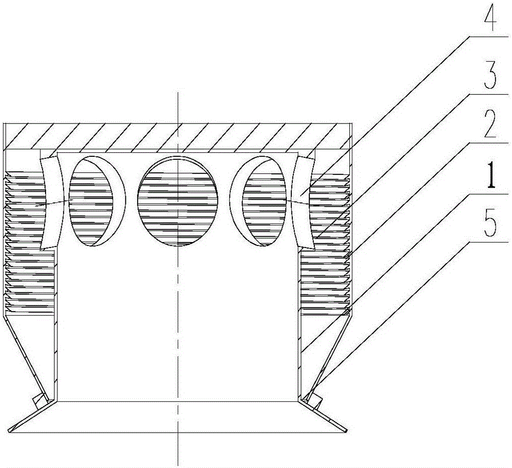
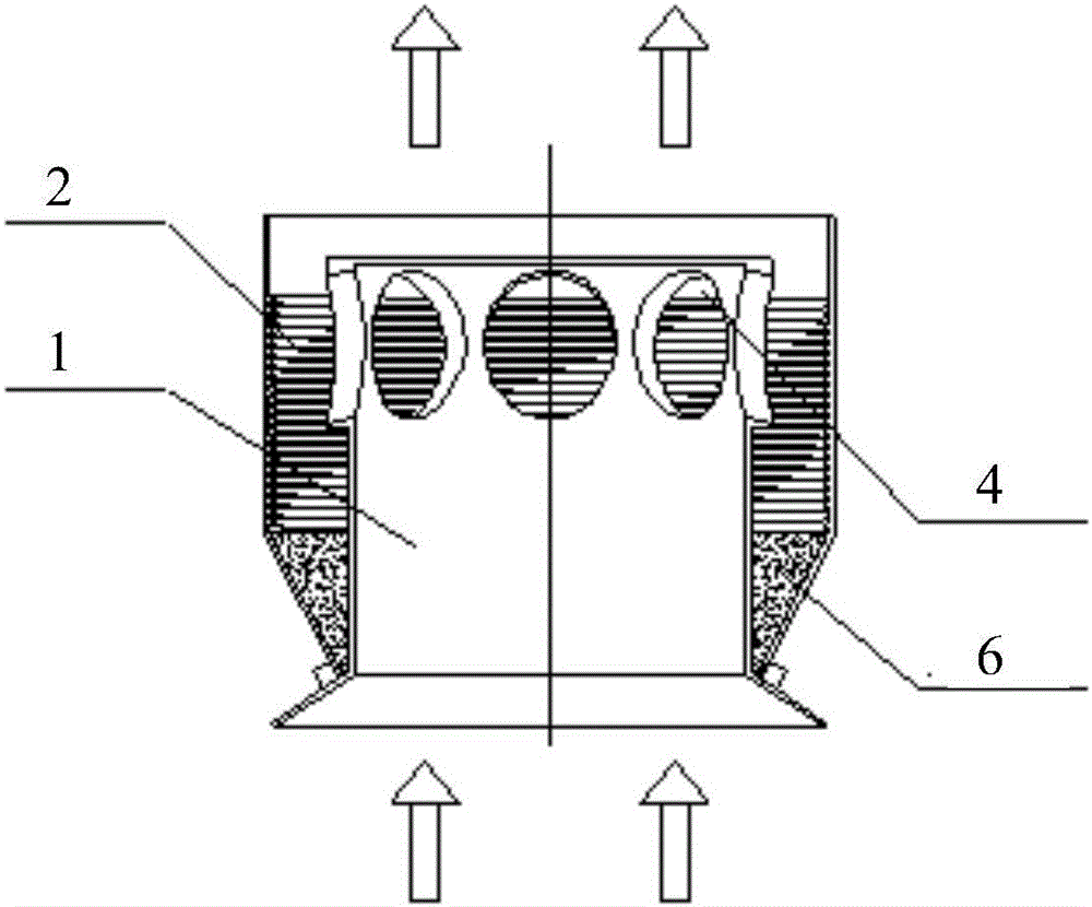
[0044] Such as figure 1 , figure 2 As shown, a hood type demister includes an inner guide cylinder 1, an outer guide cylinder 2, a spiral guide groove 3 and a guide hole 4. In order to create a flow state of high-speed rotating motion for the smoke passing through the device, a guide hole 4 is provided in the guide tube 1, and a smoke flow that moves obliquely downward at a high speed is formed through the guide hole 4; the guide The orifice 4 is a part on the guide tube in the dedusting and demisting device, and is a circular part with a certain thickness and height. A spiral guide groove 3 is provided on the inner wall of the outer guide cylinder 2 as required.

[0045] In order to discharge the collected liquid, a discharge ring hole 5 is set between the inner guide tube and the outer guide tube. The discharge ring hole is a smooth and even opening arranged at the lower part of the outer guide tube and tangent to the inner wall of the inner guide tube.

[0046] Specifi...

Embodiment 2

[0049] Embodiment 2, a hood-type demister is a flue gas flow-through part of a dedusting and demisting device, and is a vertically placed circular cylinder with a smooth inner wall and one end closed. Installed in the desulfurization absorption tower, the saturated flue gas containing a large number of mist droplets passes from bottom to top. Separation; wherein, the inner guide tube is placed vertically, and the guide holes are evenly distributed on the inner guide tube at a certain inclined angle; the outer guide tube is a circular tube with a spiral guide groove embedded in the inner wall .

[0050] Further, the determination of the diameter and height of the inner and outer guide tubes and the number of guide holes can be adjusted according to the outlet droplet control index that needs to be met.

[0051] Further, the diversion holes at the inclination angle of the inner diversion cylinder meet the actual speed of the gas rotation after diversion ≥ 8m / s.

[0052] The gu...


PUM


Abstract

The invention discloses a wind-cap type demister. The wind-cap type demister comprises an inner draft tube and an outer draft tube which covers the inner draft tube, wherein the bottom and the top of the inner draft tube are open; the wall of the inner draft tube is provided with a plurality of flow guide holes; the top of the outer draft tube is closed; the bottom of the outer draft tube is connected with the inner draft tube; the inner wall of the outer draft tube is provided with a spiral diversion trench. The wind-cap type demister is a deep dust removal and demisting device and has good dust removal and demisting effects, the outlet dust content can be below 5mg/Nm<3>, and the running resistance is less than or equal to 200Pa. The conventional demister plus wet electric precipitation process can be replaced, and a novel reliable and cheap process equipment option is provided for dust removal and demisting of saturated flue gas.

Description

technical field [0001] The invention belongs to the technical field of flue gas purification and relates to a wind cap type demister. Background technique [0002] At present, more than 95% of the flue gas of the existing large-scale coal-fired boilers in China adopts the wet desulfurization process. Contains some corrosive chemical substances, which also cause pollution and serious corrosion of the induced draft fan and flue. Therefore, the wet desulfurization process requires demisting of the absorption equipment. The purified gas must be demisted before leaving the absorption tower. . [0003] The low-temperature saturated clean flue gas discharged from large coal-fired boilers contains gypsum slurry and dust, and the configuration of GGH is very small, resulting in serious "gypsum rain" phenomenon and large dust pollution emissions. The main reason for this problem is that the existing demisters can only remove larger droplets with a particle size greater than 15um, so...

Claims


Application Information

Patent Timeline
IPC IPC(8): B01D45/04B01D45/02B01D45/12
CPCB01D45/02B01D45/04B01D45/12
Inventor 吕海生江建忠陈爱民赵成明赵晓明徐正泉肖平
Owner HUANENG CLEAN ENERGY RES INST
Why Eureka
Try Eureka