A deep dust and mist removal device

A defogging device and dedusting technology, which is applied in the direction of combined devices, dispersed particle separation, chemical instruments and methods, etc., can solve the problems of high power consumption, high construction costs, and rising operating costs, and achieve good operating effects and clean water. The effect of small water volume and low flushing frequency

Active Publication Date: 2016-12-07
BEIJING SPC ENVIRONMENT PROTECTION TECH
View PDF5 Cites 2 Cited by
  • Summary
  • Abstract
  • Description
  • Claims
  • Application Information

AI Technical Summary

Problems solved by technology

In addition, the "fog eliminator + wet electrostatic precipitator" process uses a high-voltage electric field to capture fog droplets and dust particles. There are many high-voltage electrical equipment in the equipment, and the electrode wires are made of high-grade alloy materials. The construction cost is high and the power consumption for operation is high. It is also one of the reasons that limit its application
[0007] The main reason why it is difficult to upgrade the process route of "mist eliminator + wet electrostatic precipitator" on the desulfurization tower of the built project is that the weight and volume of the equipment are huge, and the structural design strength of the original absorption tower cannot meet the load requirements of the electrostatic precipitator. ; The demand for site area also limits the possibility of its external layout when adjacently arranged, coupled with the huge increase in running resistance when adjacently arranged, resulting in a further increase in the operating cost of the "mist eliminator + wet electrostatic precipitator" process route
[0008] Due to a large number of high-voltage electrical equipment, the operation and maintenance of the "mist eliminator + wet electrostatic precipitator" process route is complicated, the technical requirements for operation are high, and the operation and maintenance costs are relatively high

Method used


Image

  • A deep dust and mist removal device
  • A deep dust and mist removal device

Examples


Embodiment 1

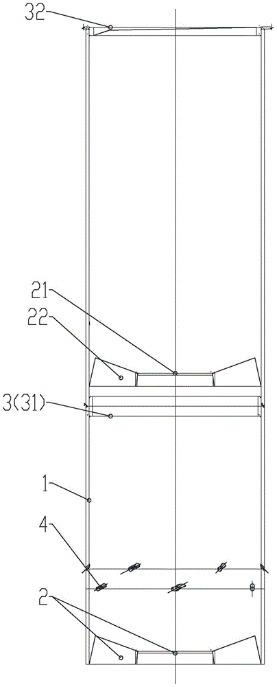
[0032] like figure 1 , figure 2 As shown, a deep dedusting and demisting device includes a guide tube 1 and a turbulent element 2 .

[0033] In order to create a flow state of high-speed rotating motion for the flue gas passing through the device, a water retaining ring 3 is also provided in the guide tube 1, and a liquid holding layer with a certain amount of stable liquid is formed through the water retaining ring 3; the said The water retaining ring 3 is a part of the liquid holding capacity of the control device of the dust removal and demisting device, which is an annular part with a certain thickness and height, and is attached in the guide tube.

[0034] In order to control the thickness of the liquid film on the wall surface of the guide cylinder for the dedusting and demisting device, a discharge hole 4 is provided on the guide cylinder. The discharge hole is an opening that is in the same rotation direction as the vane, tangent to the inner wall of the draft tube,...

Embodiment 2

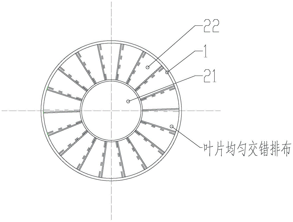
[0039] A turbulent element 2 is placed at the flue gas inlet in the guide cylinder 1; the turbulent element 2 is composed of a central cylinder 21 and blades 22. The 18 turbulent sub-blades 22 are evenly distributed in the annular area between the central cylinder 21 and the guide tube 1 at an inclination angle of 42°, and each turbulent sub-blade covers a fan-shaped area whose vertical projected coverage area is a central angle of 22°. There is a fan-shaped area overlap of 2° in other surrounding leaves.

[0040] In the turbulent flow element 2, the diameter of the central cylinder 21, the number of the blades 22, the inclination angle of the blades 22, and the size of the overlapping area of ​​the vertical projection of the blades 22 need to be determined according to the droplet content and dust content in the inlet flue gas. And export processing effect requirements to be adjusted. Generally speaking, the greater the droplet content at the inlet, the smaller the number an...


PUM


Abstract

The invention discloses an advanced dust-removing and demisting device, and particularly relates to a dust-removing and demisting device which is suitable for saturated flue gas containing a great deal of fog drops. The advanced dust-removing and demisting device has a main working principle as follows: collision among fog drop liquid particles and between fog drop liquid particles and dust particles can be realized during high-speed motion of flue gas based on the characteristic that the flue gas contains a great deal of fog drops and liquid drops, so that larger particles are formed by agglomeration and then settle; the fog drop liquid particles and the dust solid particles are in full contact with a liquid-containing layer in the device, and then separation is realized by liquid trap; the fog drop liquid particles and the dust solid particles rotate at high speed along with the flue gas, centrifugal separation is realized by virtue of the density difference between the fog drop liquid particles and the flue gas as well as between the dust particles and the flue gas, and then the fog drop liquid particles and the dust solid particles are thrown onto the surface of the inner wall of the device and are removed after contacting a liquid film layer attached onto the wall surface of the device. The advanced dust-removing and demisting device has the advantages that efficient dust removing and demisting can be realized under the conditions of low running cost and investment cost; the device is simple and reliable in structure and free of a risk of blocking, and is also portable and safe.

Description

technical field [0001] The invention relates to a deep dedusting and demisting device, in particular to a deep dedusting and demisting device suitable for saturated flue gas containing a large number of mist droplets. Background technique [0002] Dust removal and demisting of flue gas are the most common process sections in the flue gas purification process. There are various process routes, but for saturated wet flue gas containing a large number of mist droplets, dust removal and mist removal can be realized at the same time, especially high-efficiency deep dust removal and mist removal There are relatively few optional technical process routes and process equipment. The typical saturated wet flue gas containing a large number of mist droplets that needs to be dedusted and demisted is the clean flue gas that adopts the wet desulfurization process. [0003] At present, more than 95% of the flue gas of the existing large-scale coal-fired boilers in China adopts the wet des...

Claims


Application Information

Patent Timeline
Patent Type & Authority Patents(China)
IPC IPC(8): B01D50/00
Inventor 张开元贾双燕采有林
Owner BEIJING SPC ENVIRONMENT PROTECTION TECH
Why Eureka
Try Eureka