
A rotary jet aeration stirring device for a jet flotation machine

A technology for aeration stirring and flotation machines, which is applied in flotation, solid separation, etc., and can solve problems such as the influence of air suction and the fact that the rotating jet is not suitable for the aeration and agitation device of flotation machines, so as to increase the amount of aeration and improve the separation effect , arranged compact effect

Active Publication Date: 2017-12-15
UNIV OF SCI & TECH BEIJING
View PDF1 Cites 0 Cited by
  • Summary
  • Abstract
  • Description
  • Claims
  • Application Information

AI Technical Summary

Problems solved by technology

The generated rotating jet often has a central low-velocity zone near the axis, and the maximum axial velocity is not at the axis, but has a certain deviation distance from the axis, which will also affect the subsequent inhalation
Therefore, the rotating jet produced by these methods is not suitable for the aeration stirring device of the flotation machine

Method used


Image

  • A rotary jet aeration stirring device for a jet flotation machine
  • A rotary jet aeration stirring device for a jet flotation machine
  • A rotary jet aeration stirring device for a jet flotation machine

Examples


Embodiment 1

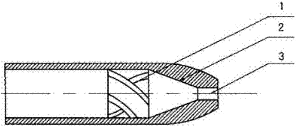
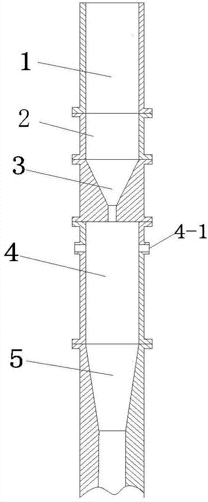
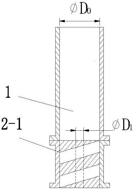
[0028] Embodiment 1: With reference to the schematic diagrams of 2, 3, 4, and 7, the rotary jet inflatable stirring device is as shown in the accompanying drawings, including a feed pipe 1, a spiral body 2-1, a conical nozzle 3, an initial mixing pipe 4, and a throat pipe 5, It is installed coaxially in sequence, and the connection method is bolted connection. The spiral body 2-1 is a cylindrical entity with a rectangular thread groove, and a straight-through circular opening is opened in the axial direction. The rectangular thread groove is built and fixed in the straight pipe, and its major diameter is equal to the diameter D of the feeding pipe. 0 , the path is d 0 , the axial free path is D 1 , the diameter of the conical nozzle is D 2 , and d 0 >D 1 >D 2 , its pitch P is 0.25D 0 ~0.5D 0 , The helix angle is 10-30°, and the number of turns is 0.5-1.5 turns.

[0029]When working, a single feeding pump can feed into one or more rotating jet aeration stirring devices ...

Embodiment 2

[0030] Embodiment 2: Referring to the schematic diagrams of 2, 5, 6, and 7, the rotary jet aeration stirring device is as shown in the accompanying drawings, including a feeding pipe 1, a rotating body 2-2, a conical nozzle 3, an initial mixing pipe 4, and a throat 5. Install coaxially in sequence, and the connection method is bolted connection. The spin body 2-2 is provided with a spin block 2-21 inside. The center of the spin body 2-21 is an axial circular flow channel, the diameter of the flow channel is equal to the diameter of the inlet of the conical nozzle 3, and the spin block 2-21 is distributed symmetrically and tangentially along the outer ring of the axial circular flow channel, forming a groove The flow channel is tangential, and the swirl block 2-21 is not inscribed with the wall of the straight pipe, and the number of swirl blocks is 4-8.

[0031] When working, a single feeding pump can feed into one or more rotating jet aeration stirring devices at the same ti...


PUM


Abstract

The invention relates to a rotary jet flow aerating agitation device for a jet flow type flotation machine. The rotary jet flow aerating agitation device comprises a feeding pipe, a rotary flow device, a conical nozzle, an initial mixing pipe and a throat pipe which are communicated from top to bottom. Due to the special structural design, when ore pulp is jetted from the nozzle, the three-dimensional speed is achieved, a rotary jet flow is formed and enters the initial mixing pipe to suck air, violent mixing is carried out, meanwhile, air constantly enters through an air inlet of the device, and the aerating process and the initial turbulence mineralization are completed. After the rotary jet flow is jetted, expansion of the rotary jet flow in fluid of surrounding is higher than that of a corresponding swirling-free jet flow, and the sucking capacity and the mixing effect of the rotary jet flow are higher than those of a common jet flow. On the basis of the working principle of the jet flow type floatation machine, the rotary jet flow aerating agitation device can improve the aerating performance and enhance bubble mineralization, and the positive effect on further improving the floatation effect is achieved.

Description

technical field [0001] The invention belongs to the field of beneficiation equipment and relates to a rotary jet aeration stirring device used in a jet flotation machine. Background technique [0002] The jet flotation machine is widely used in the sorting of various minerals, and its inflation method is realized by the entrainment effect of the high-speed jet. The slurry jet enters the mixing tube to sweep away the surrounding air, and a negative pressure is formed in the tube, so that the air continuously enters from the air inlet to complete the mixing of gas, liquid and solid. According to the working principle of the jet flotation machine, the aeration agitation device plays a decisive role in the aeration performance and separation effect of the flotation machine. The aeration of the flotation machine and the initial bubble mineralization must be completed in the aeration agitation device. The jet flotation machine is a continuous sorting operation, which requires the...

Claims


Application Information

Patent Timeline
Patent Type & Authority Patents(China)
IPC IPC(8): B03D1/24
CPCB03D1/242
Inventor 段旭琴沈丹丹陈彦丽宋猛
Owner UNIV OF SCI & TECH BEIJING
Learn More