
Manufacturing method for part with capillary-structure pipe embedded therein

A capillary structure and manufacturing method technology, applied in the field of parts manufacturing, can solve problems such as difficult to improve the heat transfer limit of parts, limit the development of microelectronic components, and difficult to handle tiny parts, etc., to achieve simple and fast manufacturing methods, speed up heat conduction efficiency, The effect of less consumables

Inactive Publication Date: 2016-06-22
CHONGQING UNIV
View PDF4 Cites 6 Cited by
  • Summary
  • Abstract
  • Description
  • Claims
  • Application Information

AI Technical Summary

Problems solved by technology

But the traditional method is difficult to deal with some tiny parts, especially the treatment of the inner surface of the parts, and even cause structural damage
With the rapid development of the microelectronics industry, the heat flux of electronic devices continues to increase. Traditional manufacturing techniques are difficult to improve the heat transfer limit of parts, which seriously limits the development of microelectronic components.

Method used


Image

  • Manufacturing method for part with capillary-structure pipe embedded therein
  • Manufacturing method for part with capillary-structure pipe embedded therein
  • Manufacturing method for part with capillary-structure pipe embedded therein

Examples


Embodiment 1

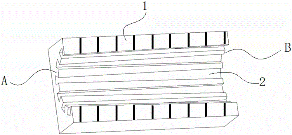
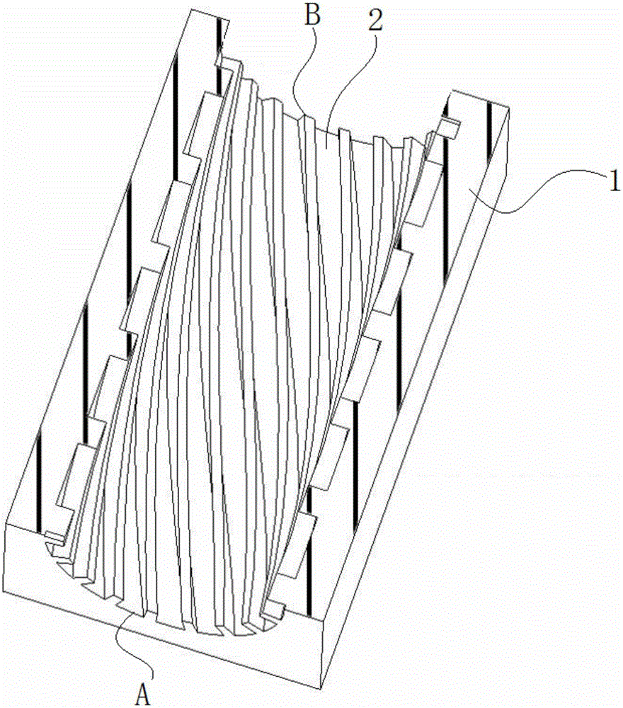
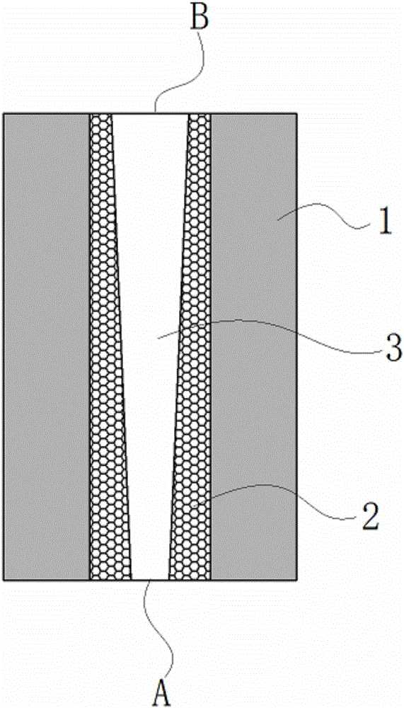
[0040] see Figure 2 to Figure 5 , at least one hollow pipe 3 is distributed inside the part 1 to be manufactured; the two outlets of the hollow pipe 3 are on the two surfaces of the part 1 respectively. One end is denoted as A terminal, and the other end is denoted as B terminal. In the embodiment, the end A is the end close to the heat source, and the end B is the end far away from the heat source.

[0041] see figure 1 or figure 2 There are several grooves 2 on the side wall of the hollow pipe. In an embodiment, the groove 2 can be like figure 1 In that way, extending from end A to end B in a straight line can also be done like figure 2 That way, it extends helically from the A end to the B end.

[0042] During manufacture, the following steps are included:

[0043] 1) Draw the model of the part 1 to be manufactured; in the model, the outlets of the A end and the B end of the pipeline 2 can be both open, and one of them can also be closed.

[0044] 2) import the m...

Embodiment 2

[0050] The main structure of this embodiment is the same as that of Embodiment 1. Further, the width of the trench 2 is gradual, that is, gradually widens from the A end to the B end.

Embodiment 3

[0052] The main structure of this embodiment is the same as that of Embodiment 1. Further, the cross section of the solid part between any two grooves 2 is rectangular, triangular, trapezoidal or circular.


PUM

PropertyMeasurementUnit
sizeaaaaaaaaaa

Abstract

The invention discloses a manufacturing method for a part with a capillary-structure pipe embedded therein. Through material additive manufacturing, the part, a pipe body and capillary structures are integrated, so that the maximum heat transfer capacity of the part is effectively improved, and the heat conduction efficiency is improved. The shape and size of the embedded pipe are flexibly designed according to the arrangement demands of a heat radiating space, and the part is especially suitable for the miniaturization development of electronic equipment. Meanwhile, the high heat conductivity formed through the capillary structures can meet the requirement of the unit area radiating amount by electronic devices with a high heat-flux density. The method also has the characteristics of being simple, rapid, low in input cost, small in material consumption and the like, and the method can be widely applied to radiating and cooling of high heat-flux density equipment such as electronic equipment, machines, chemicals and space vehicles.

Description

technical field [0001] The invention relates to the field of component manufacturing. Background technique [0002] The ability of a substance to conduct heat is called thermal conductivity. If some parts need to absorb or dissipate a lot of heat during use, materials with good thermal conductivity should be used. However, thermal conductivity is often not compatible with other properties such as mechanical properties when selecting part materials. In particular, many new materials (polymers, alloys, ceramics, etc.) developed in recent years have excellent mechanical properties, but when they are made into parts, the end close to the heat source or generating heat cannot quickly transfer heat to the end far away from the heat source. At one end, the temperature difference of the entire part is relatively large, which has a serious impact on the life of the part itself and the reliability of the entire device. [0003] In the prior art, the problem of heat dissipation of pa...

Claims


Application Information

Patent Timeline
Patent Type & Authority Applications(China)
IPC IPC(8): B22F3/11B33Y10/00B33Y80/00F28D15/04
CPCF28D15/04B22F3/1115B22F10/00B22F12/30B22F10/28B22F10/68Y02P10/25
Inventor 王杰徐华鹏张正文王茜
Owner CHONGQING UNIV
Learn More