Electromagnetic train

An electromagnetic and train technology, applied in the field of trains, can solve the problems of restricting the popularization and use of maglev trains, large power consumption of levitation magnets, low vehicle payloads, etc., and achieves the effects of reduced dead weight, light dead weight and low cost.

Active Publication Date: 2016-06-22
QUFU NORMAL UNIV +1
View PDF6 Cites 24 Cited by
  • Summary
  • Abstract
  • Description
  • Claims
  • Application Information

AI Technical Summary

Problems solved by technology

However, when the maglev train is running, the suspension gap between the stator and rotor should generally be kept at 8-10mm, and the air gap when it is parked is larger, about 15-20mm. To maintain such a suspension air gap, the excitation of the suspension magnet (rotor) The current is bound to be large, resulting in a large power consumption of the levitating magnet and a heavy weight, resulting in a low payload of the vehicle
More importantly, the maglev system is a strongly coupled, inherently nonlinear, and open-loop unstable system. During the levitation process of the train such as floating, landing, and straight running, an air gap sensor is required to monitor the size of the air gap in real time, and its control is complicated. , difficult to realize, thus limiting the popularization and use of maglev trains

Method used


Image

  • Electromagnetic train
  • Electromagnetic train
  • Electromagnetic train

Examples


Embodiment Construction

[0012] The present invention will be described in further detail below in conjunction with the accompanying drawings.

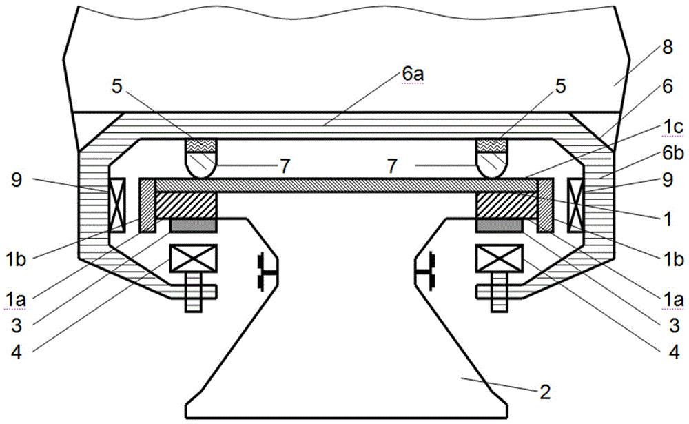
[0013] as attached figure 1 Shown, the line track of electromagnetic train of the present invention comprises track 1, reinforced concrete pier foundation 2, and its effect is to guide train advancing direction, bear train load simultaneously and pass it to foundation. Track 1 is the upper structure of the line, including stator surface 1a (for suspension), side guide rail surface 1b (for controlling the direction of the train), sliding rail surface 1c (for supporting the train) and its fixed accessories; reinforced concrete pier Foundation 2 is the substructure of the line.

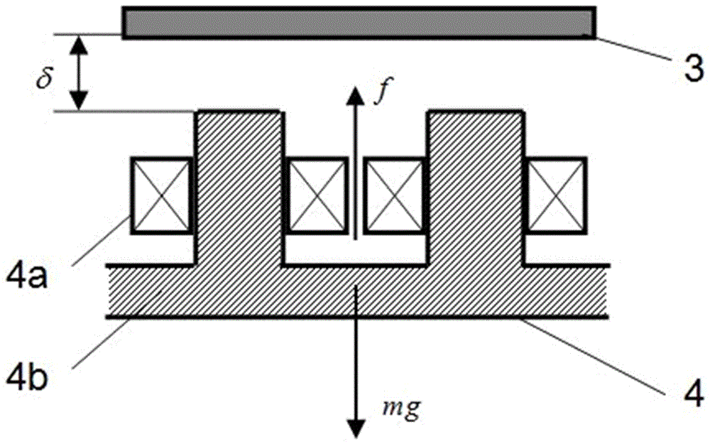
[0014] The driving system of the electromagnetic train includes a long stator 3, which is laid on both sides of the track along the entire line, and forms a long stator linear synchronous motor with the rotor 4 installed on the vehicle 8, which is used for both driving and braking. Its...


PUM


Abstract

The invention relates to an electromagnetic train. The electromagnetic train comprises a line rail, a driving system, a train body, a guiding system and an electromagnetic supporting system. A plurality of long stators are mounted on two sides of the line rail along a driving direction; the driving system comprises the long stators, and the train body comprises train body supporting racks and compartments; the guiding system comprises guiding magnets, guiding rails, guiding air gap sensors and guiding controllers; the electromagnetic supporting system comprises rotors, rotor controllers and train body load sensors, wherein the rotors are located below the long stators, and a small air gap is formed between each rotor and the corresponding long stator and ranges from 2 mm to 6 mm; and the rotor controllers adjust the exciting currents of the rotors in real time, so that the electromagnetic forces generated by the rotors are equal to the train body load. The train body is in contact with the line rail through a supporting skid at the bottom of the train body. According to the electromagnetic train provided by the invention, the air gap sensors are not needed to be suspended, so that the electromagnetic train is small in power consumption, light in self weight, low in cost and simple to control and runs stably.

Description

technical field [0001] The invention relates to a train, in particular to an electromagnetic train. Background technique [0002] Electromagnetic levitation trains have the advantage of being frictionless and have been commercially applied in Shanghai. However, when the maglev train is running, the suspension gap between the stator and rotor should generally be kept at 8-10mm, and the air gap when it is parked is larger, about 15-20mm. To maintain such a suspension air gap, the excitation of the suspension magnet (rotor) The current is bound to be large, resulting in a large power consumption of the levitating magnet and a large self-weight, resulting in a low payload of the vehicle. More importantly, the maglev system is a strongly coupled, inherently nonlinear, and open-loop unstable system. During the levitation process of the train such as floating, landing, and straight running, an air gap sensor is required to monitor the size of the air gap in real time, and its cont...

Claims


Application Information

Patent Timeline
Patent Type & Authority Applications(China)
IPC IPC(8): B60L13/04
CPCB60L13/04B60L2200/26
Inventor 蔡彬褚晓广闫绍敏王茂友
Owner QUFU NORMAL UNIV
Why Eureka
Try Eureka