Aerated grit chamber with integrated functions of grit removing, skimming and oil removing

An integrated technology of aeration and sand settling, applied in the field of aeration sand settling tanks, can solve the problems of unsatisfactory slag and sand removal effect, difficulty in meeting water output requirements, large floor space, etc. The effect of good water quality, reduced land occupation and investment

Inactive Publication Date: 2016-06-22
SHANGHAI URBAN CONSTR DESIGN RES INST GRP CO LTD
View PDF8 Cites 3 Cited by
  • Summary
  • Abstract
  • Description
  • Claims
  • Application Information

AI Technical Summary

Problems solved by technology

[0002] In recent years, due to the improvement of environmental protection standards on the effluent indicators of sewage plants, and some sewage needs to be recycled after treatment, it is difficult to meet the current effluent requirements by relying on the simple biological treatment process in the past, especially in the influent water of sewage plants. , sand content, etc. are very high, if it enters the bio-reaction system, it will be detrimental to the system, so the treatment should be strengthened to reduce operating costs and energy consumption
[0003] Many water treatment research institutions at home and abroad have conducted a lot of research work on the pretreatment reaction tank process, and developed some new and suitable sewage pretreatment structures; More and more, this way of separate construction of sewage lifting, fine grid canals, aerated grit chambers, etc. makes the equipment occupy an increasing area. In many cities, land has become a bottleneck for the development of various facilities. Many The equipment and technology cannot be implemented due to the large area occupied, and these processes are not ideal for slag and sand removal, resulting in large head loss and waste of energy consumption

Method used


Image

  • Aerated grit chamber with integrated functions of grit removing, skimming and oil removing
  • Aerated grit chamber with integrated functions of grit removing, skimming and oil removing
  • Aerated grit chamber with integrated functions of grit removing, skimming and oil removing

Examples


Embodiment Construction

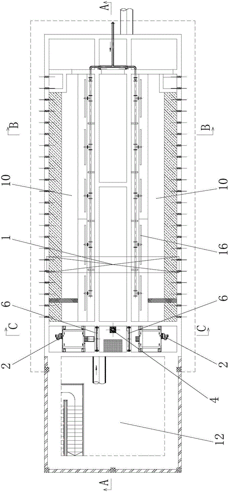
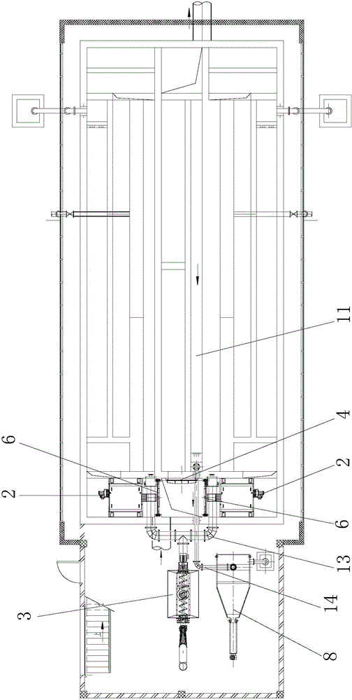
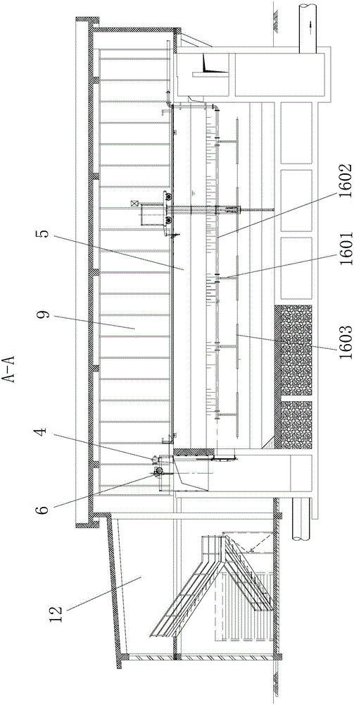
[0018] refer to Figure 1-6 , the specific implementation method adopts the following technical solutions: an aerated grit chamber integrating sand removal, scum removal and oil removal, including a double bridge sand suction machine 1, a fine grid decontamination machine 2, a screw press conveyor 3, a flashlight Dual-purpose lifting rod round gate 4, aeration grit chamber 5, electric channel gate 6, skimming device 7 and sand-water separator 8, aeration grit chamber 5 is set under the superstructure 9 of the grit chamber, aeration A grit chamber 10 and a sand discharge tank 11 are arranged in the grit chamber 5, a sand storage chamber 12 is arranged on one side of the aerated grit chamber 5, and a double bridge type sand suction machine 1 is installed above the aerated grit chamber 5 , a skimming device 7 is installed under the double-bridge sand suction machine 1, and a fine grid decontamination machine 2, a screw press conveyor 3, and a dual-purpose lifting rod circular gat...


PUM

PropertyMeasurementUnit
angleaaaaaaaaaa

Abstract

The invention discloses an aerated grit chamber with integrated functions of grit removing, skimming and oil removing and relates to a sewage treatment device. A grit settling channel and a grit discharging channel are formed in the aerated grit chamber. A grit storage chamber is arranged on one side of the aerated grit chamber; a double-bridge type grit sucker is mounted above the aerated grit chamber, and a skimming device is arranged under the double-bridge type grit sucker. Fine grating cleaners, a screw press conveyor, a manual/electric rising-stem drum gate, electric channel gates and a grit and water separator are mounted along a water feeding direction of the aerated grit chamber. The electric channel gates are mounted on two sides of the manual/electric rising-stem drum gate; one fine grating cleaner is mounted on the outer side of one electric channel gate correspondingly; the double-bridge grit sucker is connected with the screw press conveyor through a skim delivery pipe, and the grit discharging channel is connected with the grit and water separator through a grit discharging pipe. The aerated grit chamber has the advantages that skimming and grit removal are achieved integrally, maintenance and operation are facilitated, space occupation is small, energy consumption is low, and quality of outlet water is improved.

Description

technical field [0001] The invention relates to a sewage treatment device, in particular to an aeration grit chamber integrating sand removal, scum removal and oil removal. Background technique [0002] In recent years, due to the improvement of environmental protection standards on the effluent indicators of sewage plants, and some sewage needs to be recycled after treatment, it is difficult to meet the current effluent requirements by relying on the simple biological treatment process in the past, especially in the influent water of sewage plants. , Sand content, etc. are very high, if it enters the bio-reaction system, it will be detrimental to the system, so treatment should be strengthened to reduce operating costs and energy consumption. [0003] Many water treatment research institutions at home and abroad have conducted a lot of research work on the pretreatment reaction tank process, and developed some new and suitable sewage pretreatment structures; More and more,...

Claims


Application Information

Patent Timeline
Patent Type & Authority Applications(China)
IPC IPC(8): C02F1/00C02F1/24C02F1/40C02F1/52
CPCC02F1/001C02F1/24C02F1/40C02F1/52C02F2001/007
Inventor 张显忠励建全丁蓟羽吕顺
Owner SHANGHAI URBAN CONSTR DESIGN RES INST GRP CO LTD
Why Eureka
Try Eureka