Cooling device for water jet loom

A technology for water jet looms and cooling devices, which is applied in looms, textiles, textiles, and papermaking, etc. It can solve problems such as the decrease of electromagnetic pin attraction, the timing deviation of electromagnetic pin lifting, and poor weft insertion, so as to eliminate condensation. Effect

Active Publication Date: 2017-07-07
TOYOTA IND CORP
View PDF8 Cites 0 Cited by
  • Summary
  • Abstract
  • Description
  • Claims
  • Application Information

AI Technical Summary

Problems solved by technology

If the temperature of the coil rises due to self-heating of the solenoid, the attractive force on the solenoid pin will decrease, so there is a problem that the timing of lifting the solenoid pin will deviate, resulting in poor weft insertion.
In particular, if the cooled water is passed through the heat generating source like the invention of Patent Document 2, there is a possibility that knots will be generated on the structural parts of the heat generating source due to the temperature difference between the water temperature of the cooled water and the outside air temperature. Dew will affect the driving system of the heat source

Method used


Image

  • Cooling device for water jet loom
  • Cooling device for water jet loom
  • Cooling device for water jet loom

Examples


no. 1 Embodiment approach )

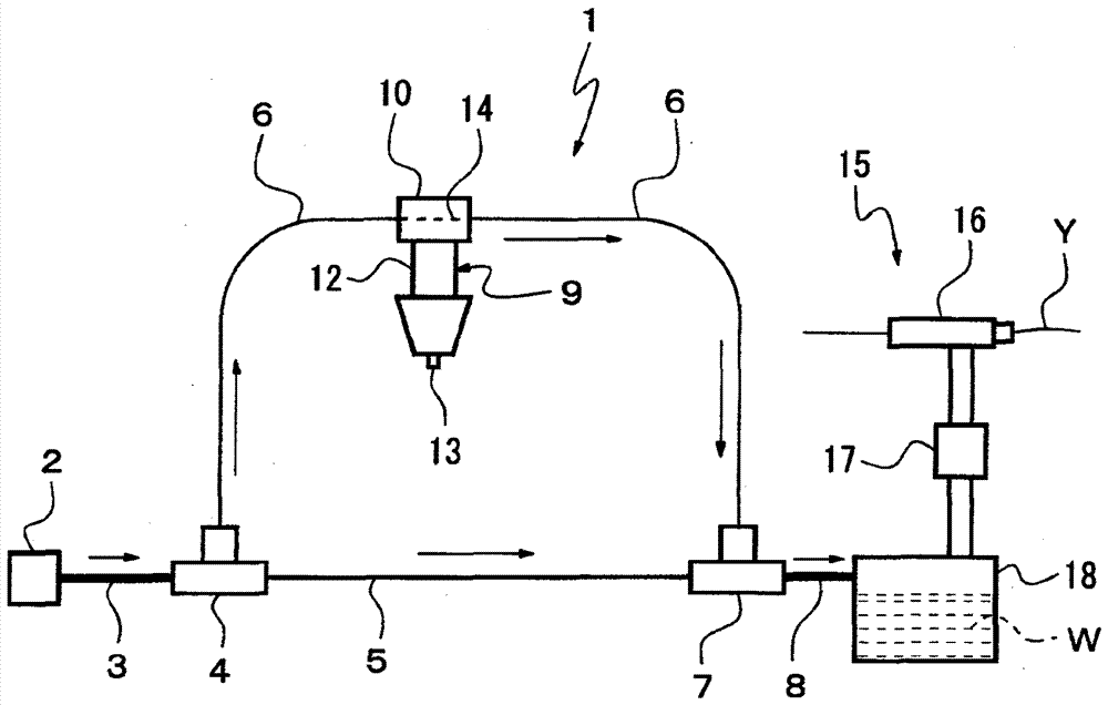
[0023] based on figure 1 and figure 2 The first embodiment will be described. figure 1 It is a block diagram showing the water supply path of the cooling device 1 in the water jet loom. In the cooling device 1 , a water supply source 2 such as a tap water pipe or a water storage tank is connected to a branch joint 4 via a water supply pipe 3 . The branch joint 4 branches the water supply element pipe 3 into a water supply main pipe 5 and a cooling water branch pipe 6 .

[0024] The water supply main pipe 5 is connected to a confluence pipe 8 by means of a manifold joint 7 . Therefore, a part of the weft insertion water W flowing through the water supply element pipe 3 is supplied to the junction pipe 8 through the water supply main pipe 5 and the collective joint 7 . The cooling water bifurcated pipe 6 connects the bifurcated joint 4 with one end of a water passage block (water passage block) 10 arranged on the weft yarn locking part 9 of the weft yarn length measuring st...

no. 2 Embodiment approach )

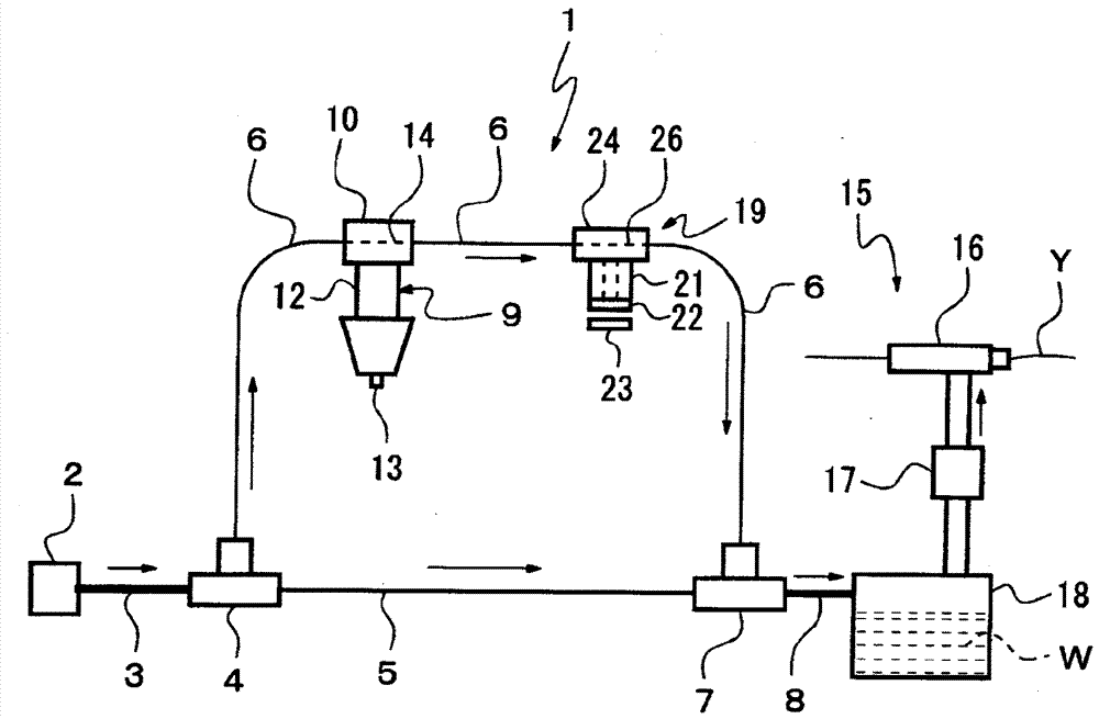
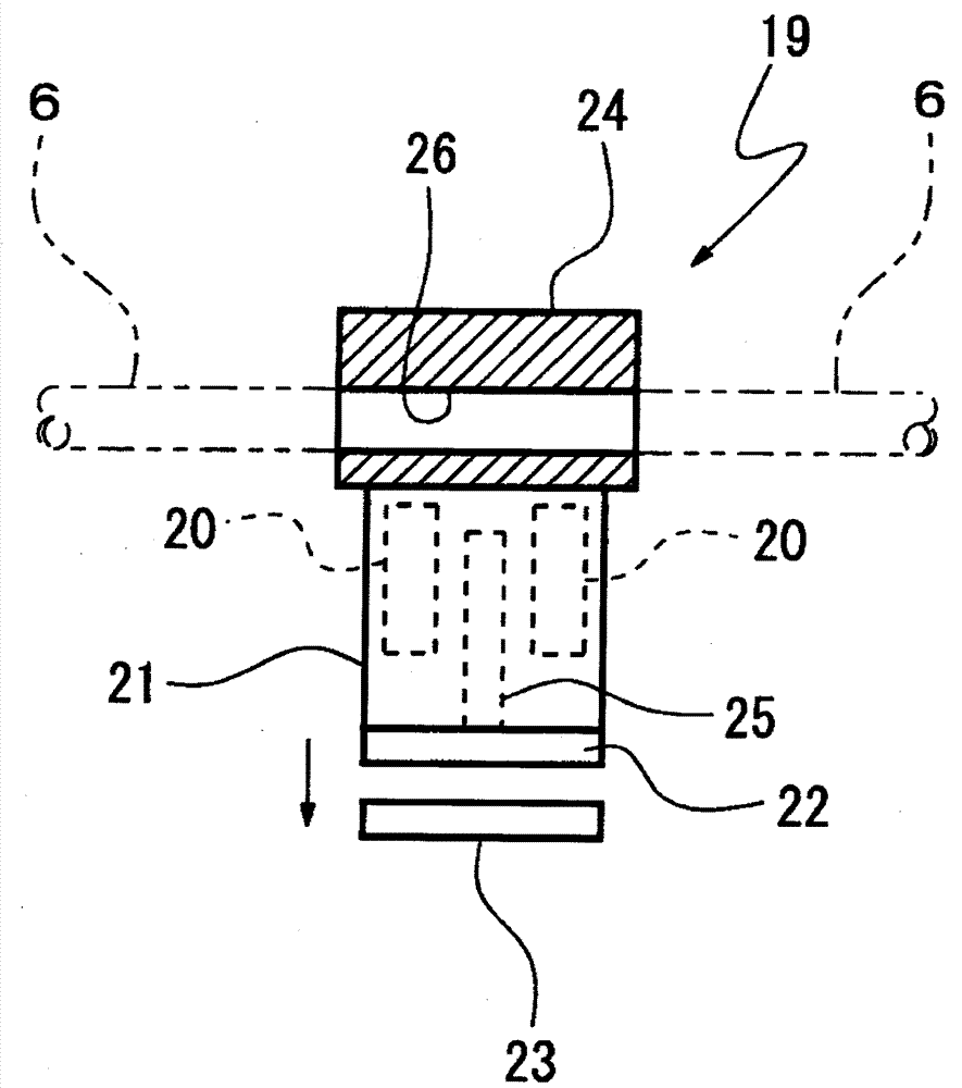
[0038] image 3 and Figure 4 The second embodiment is shown, and the same configurations as those of the first embodiment will be described with the same reference numerals, and detailed description will be omitted. The second embodiment is a structure capable of cooling the weft locking member 9 and the clamper 19 which are heat sources. The clamper 19 is arranged between the weft yarn length measuring storage device (not shown in the figure) and the weft insertion nozzle 16, and has the function of clamping the weft yarn Y after the weft insertion is completed.

[0039] Holder 19 as Figure 4 As shown in enlargement, it is composed of a main body 21, a movable clamper 22, and a fixed clamper 23. The main body 21 is equipped with a solenoid 20, and the movable clamper 22 is movably arranged at one end of the main body 21. On the side, the movable clamper 22 is flat, and the fixed clamper 23 is disposed opposite to the movable clamper 22, and the fixed clamper 23 is flat. ...


PUM


Abstract

The invention is used for utilizing the water of the weft insertion of the water spraying weaving machine, and can cool the heating source without affecting the weft insertion. The water which is supplied by the water supply source and flows inside the water supply pipe (3) is shunted to the water supply main pipe (5) and the water cooling branched pipe (6) through a branching connector (4); the pipe cooling water branching pipe; the pipe diameter of the cooling water branched pipe is set by corresponding to the weft yam clamping member; the water passing through the water passage channel of the weft yam clamping member is flown to the confluence pipe through the gathering connector; the water gathered in the confluence pipe is flown to the water supply tank (18) and appropriately supplement the water consumed by the weft insertion of the weft insertion nozzle.

Description

technical field [0001] The invention relates to a cooling device for a water jet loom. Background technique [0002] In the weft yarn storage device equipped with the loom, the weft locking member that locks the weft yarn in the storage cylinder (storage drum) lifts the electromagnetic pin from the storage cylinder by the operation of a solenoid to release the weft yarn. Solenoids usually work about 1,000 times a minute, so they generate more heat. If the temperature of the coil of the solenoid increases due to self-heating, the attractive force to the electromagnetic pin decreases, so there is a problem that the timing of lifting the electromagnetic pin varies, resulting in poor weft insertion. [0003] Patent Document 1 discloses a cooling device for a pin supporting device (corresponding to a weft locking member) of a weft yarn length measuring storage device. The weft length-measuring storage device for a water jet loom disclosed in Patent Document 1 includes a weft-ya...

Claims


Application Information

Patent Timeline
Patent Type & Authority Patents(China)
IPC IPC(8): D03D47/32
Inventor 村上达也辻本康一酒井正信
Owner TOYOTA IND CORP
Why Eureka
Try Eureka