Energy storage arrangement, temperature control unit and motor vehicle

An energy storage device and management device technology, which is applied in electric vehicles, battery temperature control, battery/fuel cell control devices, etc., can solve the damage of electric energy storage or the entire energy storage device, the operation performance damage of energy storage device, and the overheated electric energy storage device. and other problems to achieve the effect of small structure space

Active Publication Date: 2017-02-22
AUDI AG
View PDF5 Cites 0 Cited by
  • Summary
  • Abstract
  • Description
  • Claims
  • Application Information

AI Technical Summary

Problems solved by technology

Not only overheating but also overcooling impairs the operating performance of the electrical energy store and thus the entire energy storage device
In particular in connection with overheating and possibly also damage to the electrical energy store or the entire energy storage

Method used


Image

  • Energy storage arrangement, temperature control unit and motor vehicle
  • Energy storage arrangement, temperature control unit and motor vehicle

Examples


Embodiment Construction

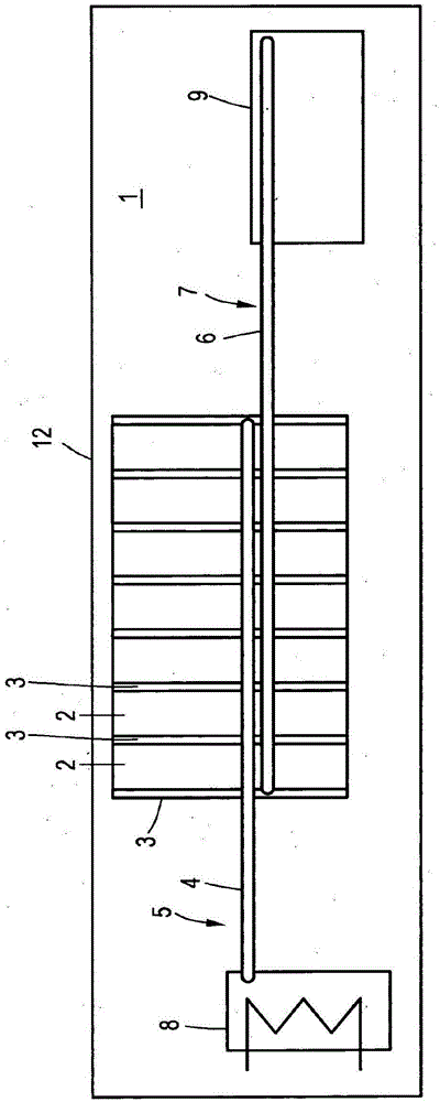
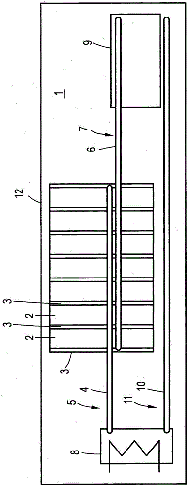
[0034] figure 1 A schematic diagram of an energy storage device 1 according to an embodiment of the invention is shown. The energy storage device 1 is part of a motor vehicle 12 , in particular a hybrid or electric vehicle, and serves to supply electrical consumers present in the motor vehicle, for example an electric drive (not shown).

[0035] The energy storage device 1 comprises a plurality of electrical energy stores 2 . The electrical energy stores 2 are electrically connected, ie connected in series or in parallel, via electrical connecting elements (not shown), in particular in the form of conductor rails or busbars (“bus bars”). In this case, the electrical connection elements are in contact with respective electrical connection means (not shown) which are arranged on a corresponding exposed outer wall section of an energy storage housing (not shown) belonging to the energy storage 2 .

[0036] The exemplary embodiments shown in the figures show that the square or p...


PUM


Abstract

The invention concerns an energy storage arrangement (1) comprising a plurality of electrical energy stores (2), wherein between at least two electrical energy stores (2) there is arranged or configured at least one thermally conductive spacer element (3) that provides a spacing, at least in sections, between the at least two electrical energy stores (2), the at least one spacer element (3) being thermally coupled to at least one heat pipe (4) of a first heat pipe arrangement (5) that comprises at least one heat pipe (4), the at least one spacer element (3) also being thermally coupled to at least one heat pipe (6) of a second heat pipe arrangement (7) that comprises at least one heat pipe (6).

Description

technical field [0001] The invention relates to an energy storage device comprising a plurality of electrical energy stores, wherein at least one thermally conductive spacer element is arranged or formed between at least two electrical energy stores, at least partially separating the at least two electrical energy stores from one another, wherein The at least one spacer element is thermally coupled to at least one heat pipe of a first heat pipe arrangement comprising at least one heat pipe. Background technique [0002] Corresponding energy storage devices are known and are used, for example, in the field of motor vehicle technology to supply electrical consumers. Such an energy storage device comprises a plurality of electrical energy stores electrically connected to one another. Such an electrical energy store can be, for example, a lithium-ion energy store or a lithium-ion battery. Typically, spacer elements are arranged between the electrical energy stores, which space...

Claims


Application Information

Patent Timeline
Patent Type & Authority Applications(China)
IPC IPC(8): H01M10/60H01M10/625H01M10/6552B60L11/18H01M50/209
CPCH01M10/60H01M10/625H01M10/6552B60L58/24H01M50/209H01M10/615H01M10/653H01M10/6555H01M10/667H01M10/613Y02T10/70Y02E60/10H01M10/6569H01M2220/20
Inventor J·史密斯M·辛特伯格C·阿尔曼B·海伦塔尔
Owner AUDI AG
Why Eureka
Try Eureka