
Device for heat transfer between two walls

a technology for heat transfer and two walls, applied in indirect heat exchangers, lighting and heating apparatus, heating types, etc., can solve problems such as not being able to solve all known devices, and achieve the effect of preventing heat exchang

Inactive Publication Date: 2005-03-01
RYLEWSKI EUGENIUSZ
View PDF11 Cites 11 Cited by
  • Summary
  • Abstract
  • Description
  • Claims
  • Application Information

AI Technical Summary

Benefits of technology

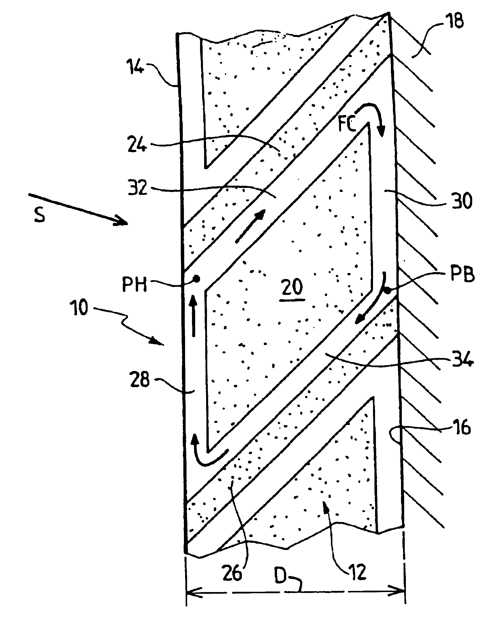
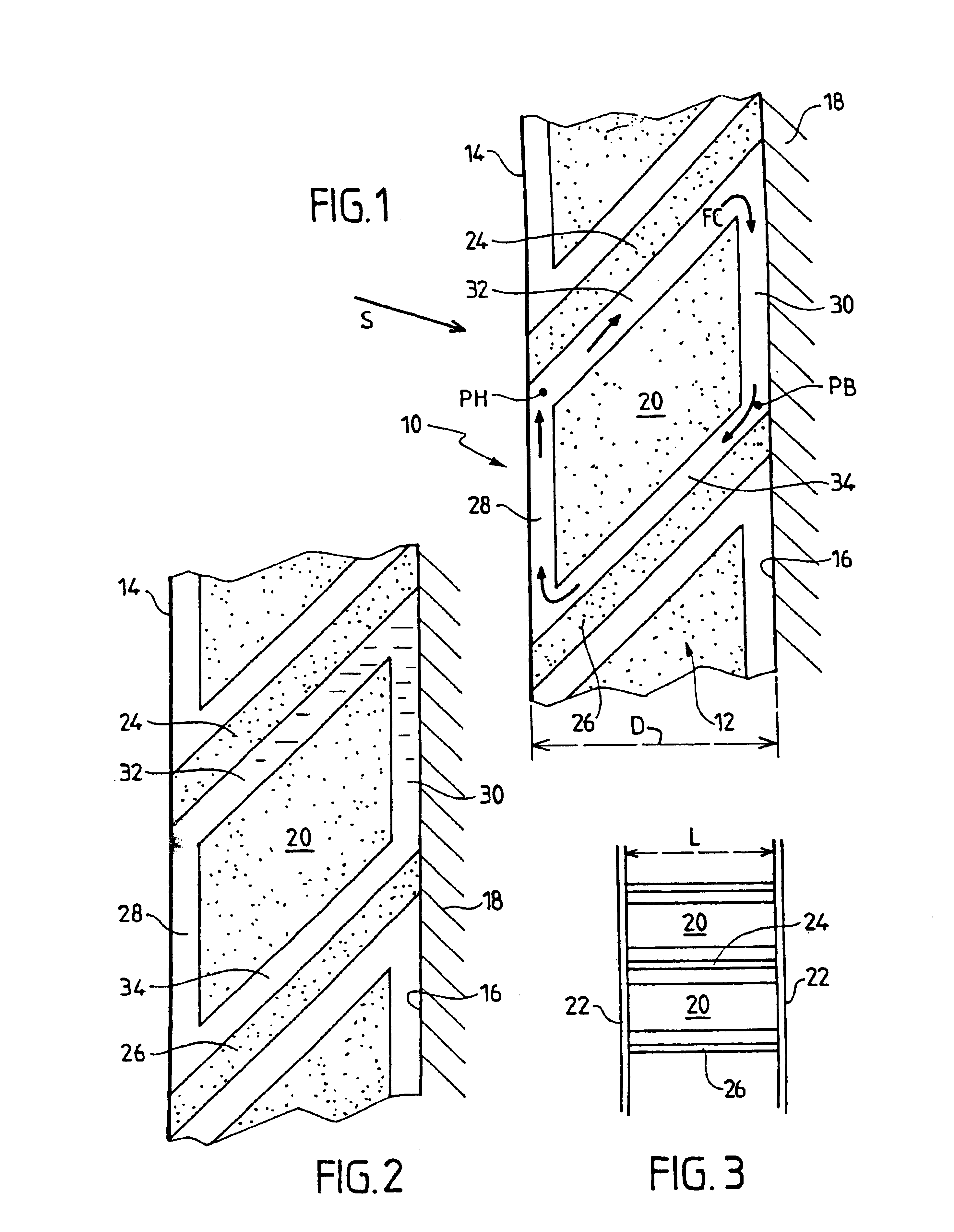
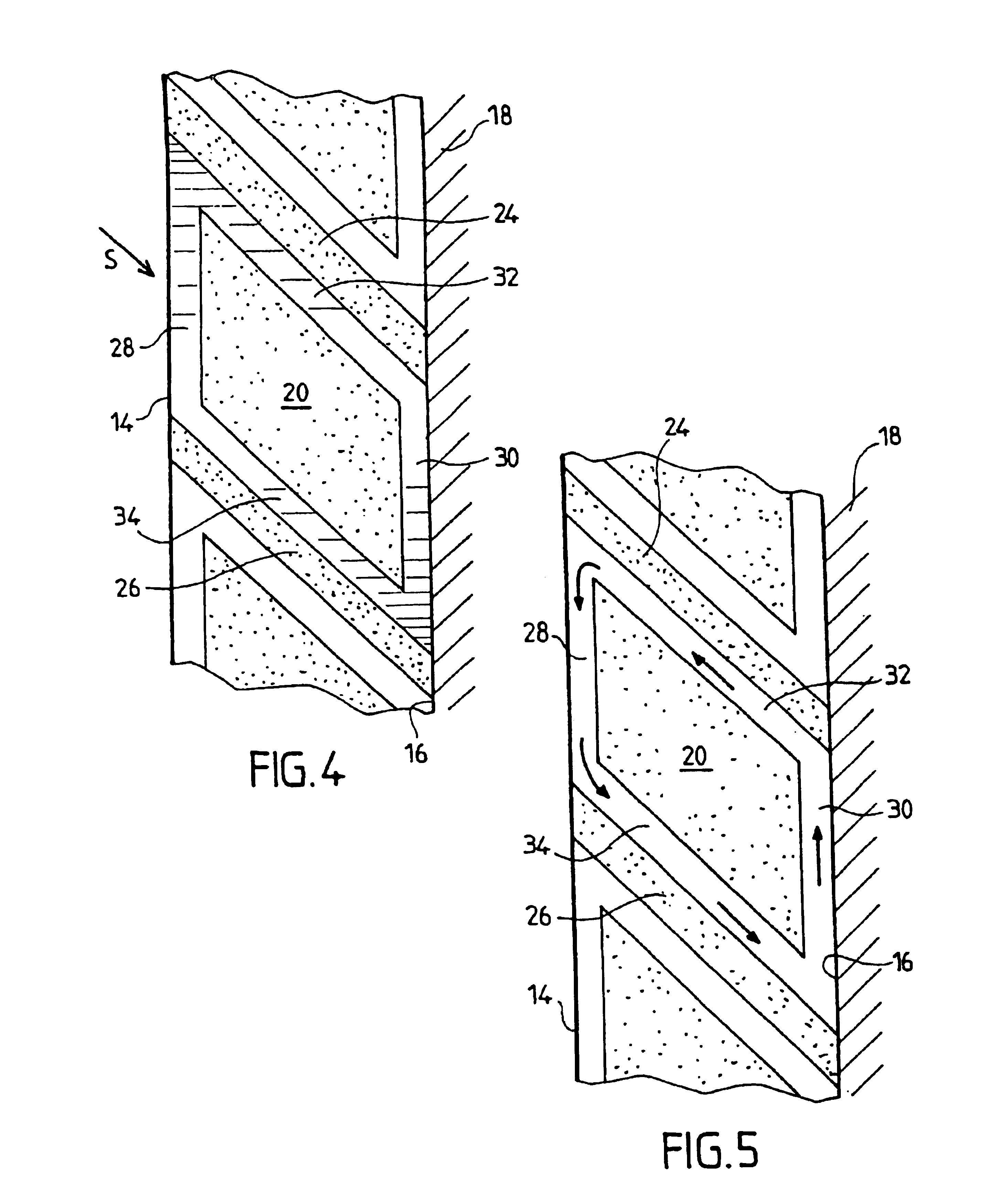
This heat transfer device, which has numerous applications, makes it possible by virtue of the configuration of the channels, and in particular of the vertical staggering of the first channel and second channel, to allow or prevent circulation of the heat-exchanging fluid by simple convection movement, and this according to the respective temperatures of the first and second channels.
In one embodiment of the invention, the first channel forms a low channel and the second channel forms a high channel, which makes it possible to effect a heat exchange when the temperature of the first channel is higher than that of the second channel, and to prevent a heat exchange when the temperature of the first channel is lower than that of the second channel.
In another embodiment, the first channel forms a high channel and the second channel forms a low channel, which makes it possible to effect a heat exchange when the temperature of the first channel is lower than that of the second channel and to prevent a heat exchange when the temperature of the first channel is higher than that of the second channel.

Problems solved by technology

The known devices do not always make it possible to solve all the situations that arise in practice and are generally limited to the heating of one wall and one associated thermal mass on the basis of solar radiation and thermal insulation of this thermal mass when the solar radiation has stopped.

Method used


Image

  • Device for heat transfer between two walls
  • Device for heat transfer between two walls
  • Device for heat transfer between two walls

Examples


Embodiment Construction

FIG. 1 will be referred to first, which shows a device 10 according to the invention comprising an insulating unit 12 capable of being interposed between a first wall 14 and a second wall 16.

In the example, the wall 14 forms an outer wall capable of being exposed to solar radiation S, whereas the wall 16 forms part of a wall 18 of a building. The walls 14 and 16 are substantially vertical and are located at a distance D which may, for example, be between 100 and 200 mm.

The wall 14 may, in its simplest form, consist of a plain sheet of metal, e.g. coated with a black paint.

The unit 12 comprises at least one insulating core 20, which has in straight vertical section substantially the shape of a parallelogram. This insulating core 20 is housed for example between two vertical columns 22 (FIG. 3) forming a frame. This insulating core 20 is placed between the first wall and the second wall, but without coming into contact with them. The unit further comprises an upper insulating partitio...


PUM


Abstract

The invention concerns a heat transfer device comprising an insulating module (12) designed to be inserted between a first wall (14) and a second wall (16) to define a closed loop wherein flows a heating medium (FC) which comprises a first channel (28) extending substantially vertically along the first wall (14) and a second channel (30) extending substantially vertically along the second wall (16), the first channel and the second channel being mutually offset in the vertical direction to define a low channel and a high channel, as well as an upper channel (32) and a lower channel (34) linking the first channel and the second channel, such that heating medium (FC) flows freely or is blocked naturally in the loop when on the basis of the respective temperatures of the high channel and the low channel. The invention is particularly useful for heating or cooling buildings.

Description

BACKGROUND OF THE INVENTION1. Field of the InventionThe invention relates to a device for heat transfer between a first wall and a second wall, which are respectively in contact with a first thermal mass and a second thermal mass.2. Description of the Related ArtDevices of this type are already known which are used in particular for transferring heat between a wall capable of being heated by solar radiation and another wall, such as a wall of a building for example, a water reservoir etc. In this case, one of the thermal masses is the external ambient air, whereas the other thermal mass is the building, reservoir, etc.In this special application, such devices must be able to transfer the heat originating from solar radiation to the wall to be heated, whilst preventing a thermal transfer in the opposite direction when the solar radiation has stopped.The known devices do not always make it possible to solve all the situations that arise in practice and are generally limited to the hea...

Claims


Application Information

Patent Timeline
Patent Type & Authority Patents(United States)
IPC IPC(8): F24J2/04E04B1/74F24S23/00F24F5/00F24S90/00F28D21/00
CPCF24J2/0444F24J2002/4605F28F2013/008Y02B10/24Y02E10/44Y02B10/20Y02A30/272F24S20/66F24S2080/07Y02E10/40
Inventor RYLEWSKI, EUGENIUSZ
Owner RYLEWSKI EUGENIUSZ
Learn More