Test apparatus for testing substrates at low temperatures

a technology of test apparatus and substrate, which is applied in the direction of electronic circuit testing, measurement devices, instruments, etc., can solve the problems of limiting the possible low temperature range for the testing of electronic components, affecting the accuracy of test results, and requiring a large amount of time and labor

Inactive Publication Date: 2006-05-16
CASCADE MICROTECH
View PDF12 Cites 12 Cited by
  • Summary
  • Abstract
  • Description
  • Claims
  • Application Information

AI Technical Summary

Benefits of technology

[0010]According to the invention, the object is achieved by virtue of the fact that there is a vacuum chamber which surrounds the working area of the chuck and is connected to a vacuum pump, and that one side of the chuck is thermally decoupled from the uncooled chuck drive and the other side of the chuck is thermally connected in a releasable manner to the test substrate. The test substrate is shielded from the thermal radiation of the surrounding uncooled assemblies by means of a directly cooled thermal radiation shield. The production of a vacuum in the working area makes it possible to test more components than were described in the introduction. In particular, it is now possible to test the oscillation behavior of micromechanical components or optical switches, since the presence of immobile and moving gases in the test environment influences the oscillation behavior of the components themselves or causes oscillations in the test atmosphere to be superimposed on the test variable.
[0011]The thermal decoupling of the chuck drive from the cooled chuck allows a motorized X-Y table to be used as a chuck drive, even at very low temperatures. Consequently, the chuck drive can be controlled very easily by an operating element outside the vacuum chamber, and the mobility of the X-Y table is not restricted by the low temperature of the moving parts. Furthermore, the stepper motors of the X-Y table allow the chuck to be positioned with an accuracy and reproducibility of a few micrometers without problems despite the presence of rigid coolant lines.
[0012]Furthermore, the thermal decoupling of the chuck, together with a reduction in the number of components to be cooled, leads to an increase in the stability and accuracy of the temperature regime and to a reduction in the coolant consumption. By virtue of the fact that heat exchange with the environment through convection is prevented, in particular the production of a vacuum in the working area accelerates the cooling process.

Problems solved by technology

However, these test conditions restrict the possible low temperature range for the testing of electronic components.
In the test apparatus described, the cooled chuck drive constitutes a particular drawback, since the positioning of the chuck relative to the probes can only be effected with the reproducibility and accuracy required for the test substrate with considerable outlay on time and labor.
The media connections and lines, which are relatively rigid at relatively low temperatures, further exacerbate this drawback.
A further drawback consists in the fact that the temperature of the test substrate is influenced by the surrounding components of the test apparatus, the temperature of which has been set very differently by the various heat exchange processes in the equilibrium state.
For example, high levels of heat are introduced into the test substrate as a result of uncontrollable thermal radiation and convection from the surrounding hot components, which has a significant adverse effect on the accuracy and reproducibility of the testing.
Secondly, the contact between the test substrate and the warmer probes leads to a temperature drift at the substrate and therefore to a change in the test conditions.
These facts also have a significant adverse effect on the accuracy and reproducibility of the testing at relatively low temperatures.

Method used


Image

  • Test apparatus for testing substrates at low temperatures
  • Test apparatus for testing substrates at low temperatures
  • Test apparatus for testing substrates at low temperatures

Examples


Embodiment Construction

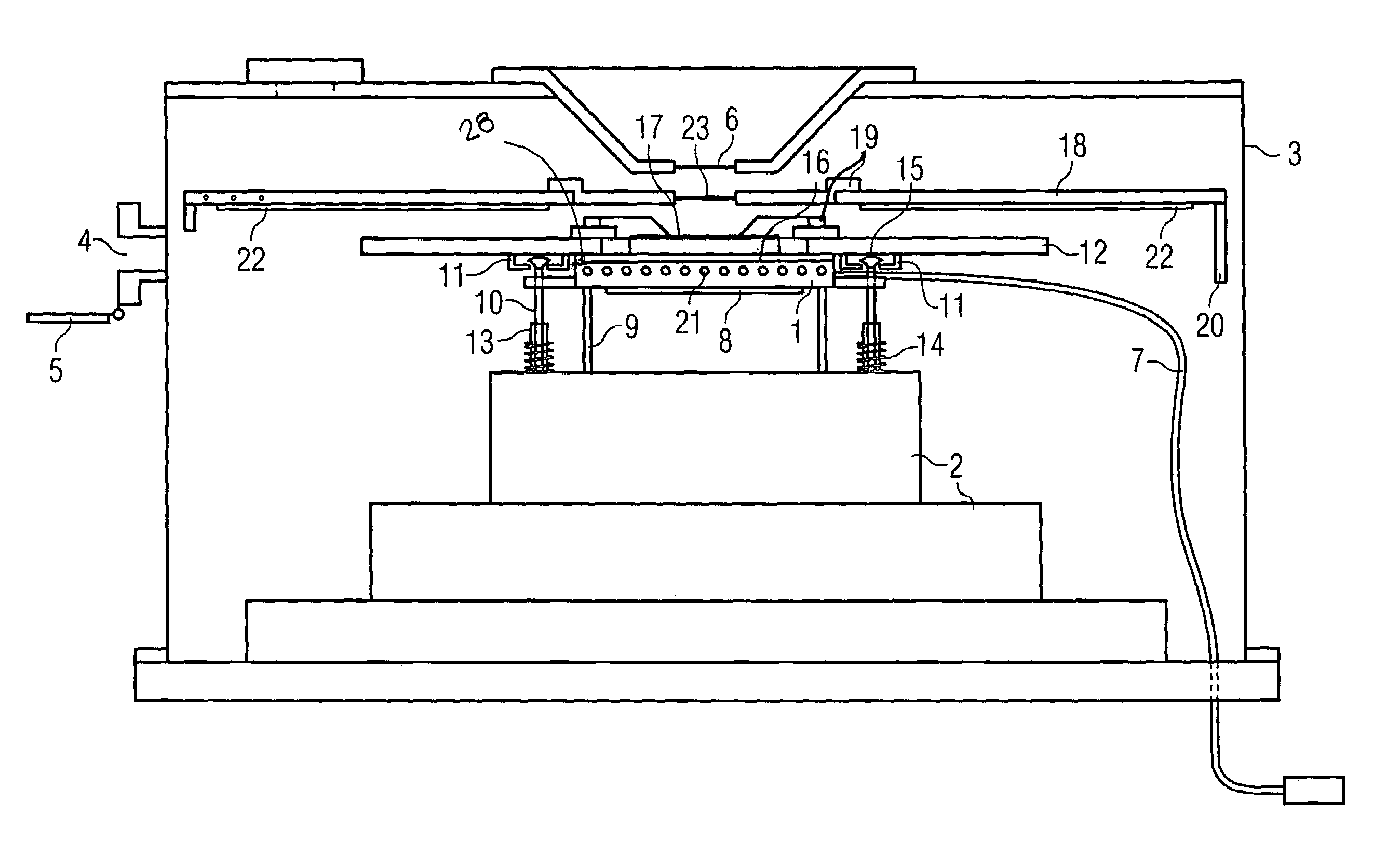
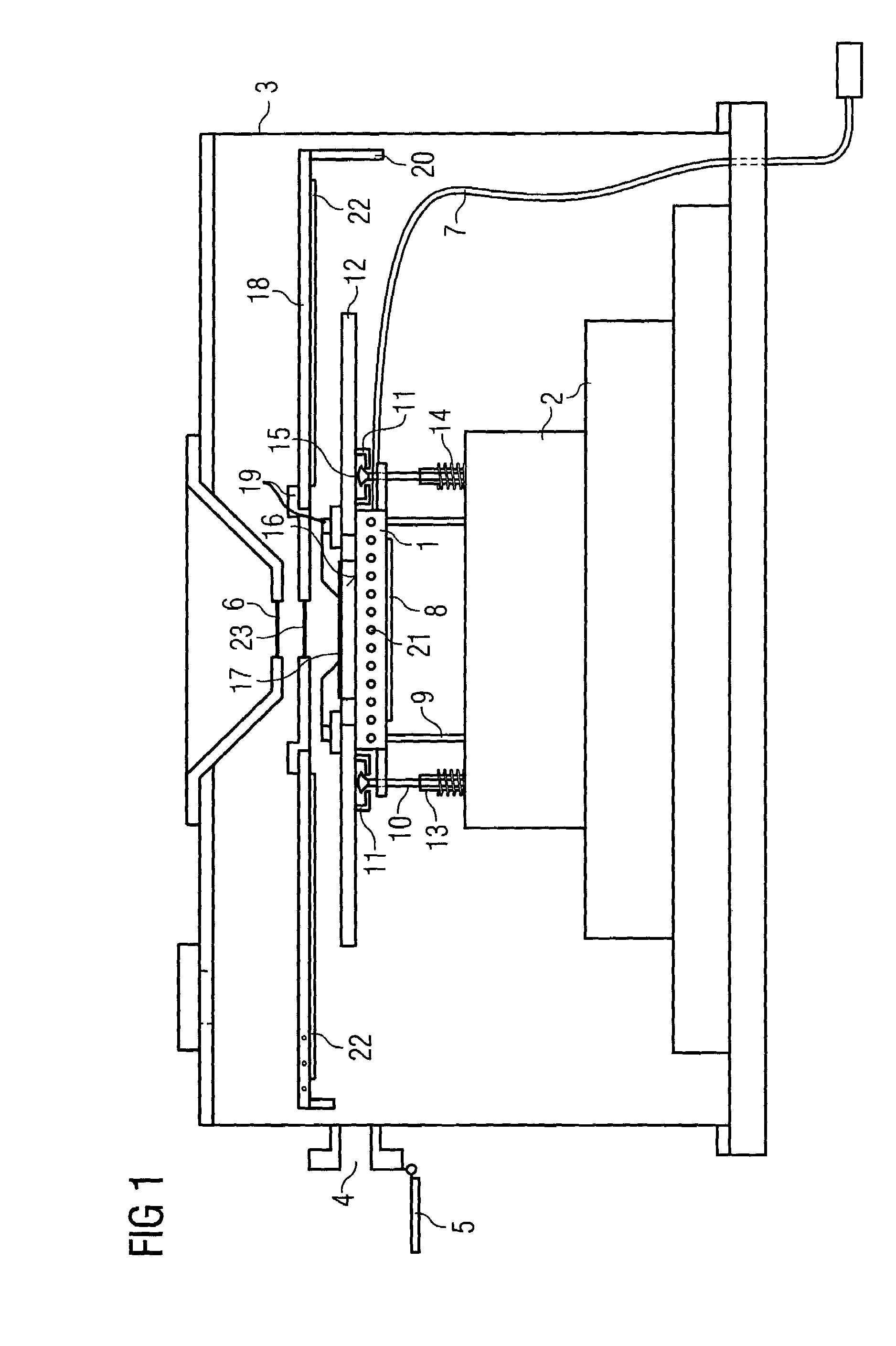
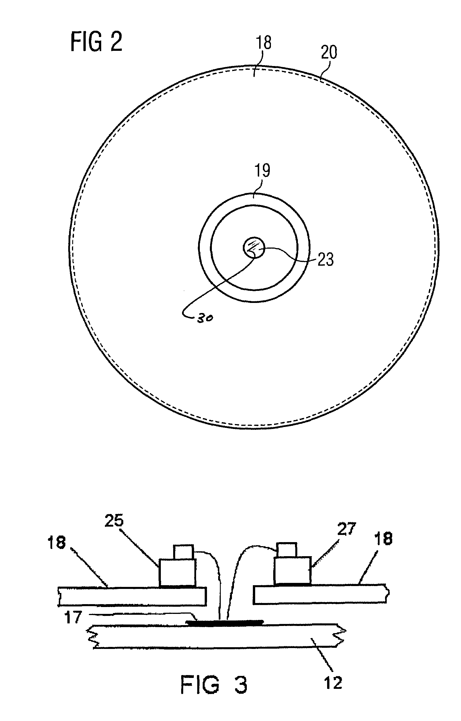
[0034]As illustrated in FIG. 1, a test apparatus for low-temperature testing, known as a cryotest apparatus, has a chuck 1, which is connected to a chuck drive 2, preferably a motorized X-Y table. The chuck 1 can be displaced in the working area by means of the chuck drive 2. The working area is surrounded by a vacuum chamber 3, which on one side has a loading opening 4, which can be closed off in a vacuum-tight manner by a flap 5, and centrally above the working area has an inspection opening 6, which is closed off by quartz glass which reflects infrared radiation. The working area is connected to a vacuum unit for evacuating the working area.

[0035]The cylindrical chuck 1 consists of copper with a gold coating, is connected to a coolant tank via the flexible coolant line 7, and, depending on the coolant used, can be cooled to various temperature ranges as a result of the coolant being passed through passages 21 which are present in the interior of the chuck 1. The underside of the ...


PUM


Abstract

A test apparatuss for testing substrates at low temperatures has a chuck, which can be displaced in the working area by means of a chuck drive, the temperature of which can be controlled using heating and cooling means. The chuck has a receiving surface for receiving a test substrate and holding means for fixing a substrate carrier which receives the test substrate. Spatially and thermally defined test conditions are maintained with minimal energy and labor costs both at room temperatures and at low temperatures. This is achieved by providing a vacuum chamber which surrounds the working area of the chuck. The chuck is on one side thermally decoupled from the uncooled chuck drive and on the other side is thermally connected in a releasable manner to the test substrate. The cooled chuck and the cooled test substrate are shielded from the thermal radiation of the surrounding uncooled assemblies by means of a directly cooled thermal radiation shield.

Description

BACKGROUND OF THE INVENTION[0001]This application is related to the subject matter of commonly owned, co-pending application Ser. No. 10 / 677,524, filed on even date herewith, the specification of which is incorporated herein by reference.[0002]The invention relates to a test apparatus for testing substrates at low temperatures, having a chuck, which can be displaced in the working area by means of a chuck drive and can be cooled using suitable cooling apparatus. The test apparatus includes a receiving surface for receiving a test substrate, comprising a substrate carrier and component to be tested, and a holding arrangement for receiving the substrate carrier.[0003]The test substrate may comprise either semiconductor chips which are still joined to the wafer, or individual components, such as semiconductor chips, hybrid components, micromechanical components or the like. The substrate has a smooth and planar underside and is arranged and held, at least indirectly, on the chuck, whic...

Claims


Application Information

Patent Timeline
Patent Type & Authority Patents(United States)
IPC IPC(8): G01R31/02G01R31/28
CPCG01R31/2887G01R31/2865G01R31/2806G01R31/2831
Inventor SCHNEIDEWIND, STEFANDIETRICH, CLAUSKIESEWETTER, JORGWERNER, FRANK-MICHAELSCHMIDT, AXELZIEGER, MATTHIAS
Owner CASCADE MICROTECH
Why Eureka
Try Eureka