Liquid-Vapor Separating Method and a Liquid-Vapor Separating Type Evaporator

a liquid-vapor separation and separating method technology, applied in the direction of indirect heat exchangers, separation processes, lighting and heating apparatus, etc., can solve the problems of reducing the efficiency of surface enhancement, affecting the efficiency of heat exchange formation, and the inner wall of the tube cannot be well wetted by liquid, so as to reduce the consumption of materials, improve the efficiency of energy conversion and utilization, and reduce the power of the compressor

Inactive Publication Date: 2010-05-27
TSINGHUA UNIV
View PDF13 Cites 12 Cited by
  • Summary
  • Abstract
  • Description
  • Claims
  • Application Information

AI Technical Summary

Benefits of technology

[0021]The present invention is characterized by the following advantages due to the above technical measures: 1) the present invention employs a separation device to partition the heat exchange tube into a liquid evaporation segment and a steam superheat segment in a non-seal manner, thus preventing the incoming liquid from entering the superheat segment directly-which will influence the operation of the evaporator, while enabling the control of the superheat degree of the leaving steam-which is difficult to be implemented by traditional evaporators. The present evaporator can control the temperature of superheat steam according to the requirements to specified superheat degrees. Compared to adding the length of tube in the prior art, the separation device of the present invention has advantages in reducing the consumption of materials, improving the efficiency of energy conversion and utilization, and decreasing the power of the compressor of a refrigeration system. 2) By employing a reflux tube filled with porous core for the drainage and recirculation of residual evaporated liquid, which has dual functions in drawing and blocking liquid by capillarity, thus making the residual liquid gathering at the main body of the flow of the evaporation liquid, the present invention can realize recycling of the residual liquid, thus having advantages for auto-recycling residual liquid and re-evaporating the residual liquid, and eliminating the problem of accumulation and discharge of residual liquid. At the same time, the present invention can prevent the main body of the liquid flow from entering into the main heat exchange and evaporation section, which may result in degraded operation of the evaporator. Thus the efficiency and adaptability of the evaporator can be improved. 3) The present invention provides a novel liquid-vapor-separation device which can fast discharge the vapor from evaporation via a discharge tube thus reducing the pressure drop in the system helping to reach a higher efficiency of the evaporation process. 4) The present invention utilizes an inner tube bundle structure to circulate evaporated liquid (refrigerant) between an outer tube and an inner tube, with the complex inner features of the structure, and the present invention not only enhances the disturbance to the liquid flow, but also reduces the liquid by transferring it into vapor. Reducing the liquid is helpful to the wetting of liquid film, and the evaporation of a thin liquid film with better heat exchange effect is formed, thus the heat exchange is enhanced. 5) The evaporation surface is designed with micro-threads, grooves, and a porous layer, where the micro-threads or grooves covered with a porous layer are formed by sintering a plurality of screen and metal or non-metal particles. By the capillarity of the porous structure, the inner wall of the tube can be wetted by the liquid and the evaporation of a thin liquid film with a better heat exchange effect can be reached and the effect of surface enhancement can be further improved. Moreover, the porous layer can improve venting of the vapor of the surface area inside the tube and supplying of liquid to the surface area; a similar effect can be made to the outer surface of the heat exchange tube by similar measures. 6) The present invention has advantages for better efficiency of evaporation, high exchange transfer coefficient, small heat exchanger size, and low consumption of metal. Compared with prior art, the present invention can save more than 20% in materials, and provide lower manufacturing and operation costs, and a more simple manufacturing process.

Problems solved by technology

But the evaporation in the tube of the prior art can result in a more complex two-phase flow which disadvantages the formation of modality with efficient heat exchange.
The layered flow will result in local dryout and congregating of liquid at the bottom of the tube, thus the surface of the inner wall of the tube can not be well wetted by the liquid.
Therefore uneven boiling or surface evaporation will be formed, or non-perfect boiling or surface evaporation will be formed, and as a result, the effect of surface enhancement will be weakened and the heat exchange efficiency will be reduced.
Annular flow and thin liquid film have advantages in heat exchange, but they account for a limited percentage in the whole flow process, and thus have a limited effect on heat transfer.
On the other hand, evaporation and boiling in a single tube flow process will result in a complex two-phase flow of vapor and liquid.
When a two-phase flow occurs, bubbling, vapor blocking, annular flow, or stratified flow may occur in the flow depending on local vapor quality, thus substantially increasing the flow resistance and instability.
As a result, the system stability, flow resistance and system adjustment are adversely affected.

Method used


Image

  • Liquid-Vapor Separating Method and a Liquid-Vapor Separating Type Evaporator
  • Liquid-Vapor Separating Method and a Liquid-Vapor Separating Type Evaporator
  • Liquid-Vapor Separating Method and a Liquid-Vapor Separating Type Evaporator

Examples


embodiment 1

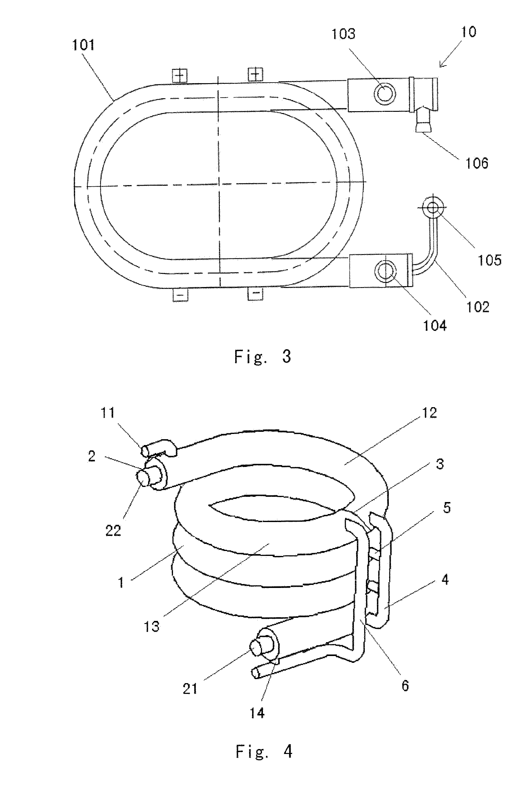
A Liquid-Vapor-Separation-Outside-Spiral-Tube Evaporator

[0034]As shown in FIG. 4, the present embodiment comprises a spiral outer tube 1, and an inner tube 2 positioned in the outer tube 1, the inner tube 2 of present embodiment is an inner tube bundle with spiral configuration (as shown in FIG. 5), which can effectively improve the wetting and disturbance of the liquid while enhancing the heat exchange and the evaporation of the thin liquid film. As shown in FIG. 4, both ends of the outer tube 1 connect the outer wall of the inner tube 2 hermetically, the bottom port of the inner tube 2 is used as the inlet 21 of heating fluid, the top port of the inner tube 2 is used as the outlet 22 of heating fluid, and the steam outlet 11 of the outer tube 1 is positioned at the tube wall of the top port of the outer tube 1. Between the upmost outer tube 1 and the inner tube 2, an annular separation plate is set as a separation device 3 which partitions the outer tube 1 into a superheat segment...

embodiment 2

A Liquid-Vapor-Separation-Outside-Vertical-Serpentine-Tube Evaporator

[0037]As shown in FIG. 6, the main difference between this embodiment and the embodiment 1 lies in that the present embodiment employs a vertical serpentine outer tube 1 and a corresponding inner tube 2 as a separation device 3 positioned between the layer 1 and layer 2, and makes the first layer of outer tube 1 a superheat segment 12 and the downstream of the second layer of outer tube 1 an evaporation segment 13. Alternatively, the separation device can be positioned between the third layer and the fourth layer, and the actual position of the separation device can be determined according to requirement of the superheat degree. A liquid-vapor-separation tube 4 is connected to the superheat segment 12 near the separation device 3, and a steam drainage tube 5 connects the liquid-vapor-separation tube 4 with each layer of outer tube 1 at the evaporation segment 13. An incoming tube 6 for evaporated liquid connects to...

embodiment 3

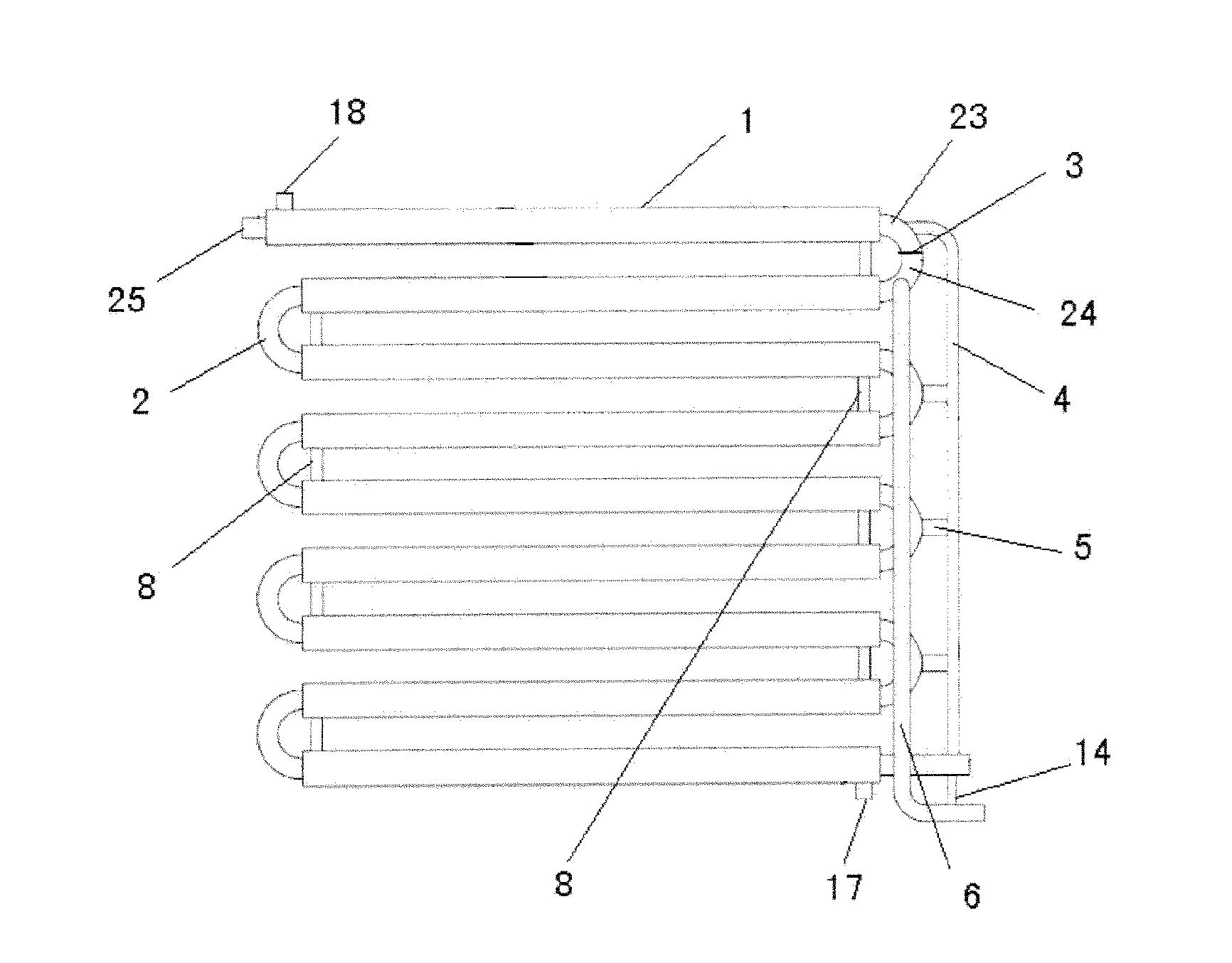
A Liquid-Vapor-Separation-Inside-Vertical-Serpentine-Air-Heating Evaporator

[0039]As shown in FIG. 7, the present embodiment has a vertical serpentine tube similar to that of embodiment 2, but a single layer tube referred to as inner tube 2 is employed due to air used as heating fluid. Outside fins 7 are set between each layer of inner tube 2 via expanded joints, and the separation device 3 partitions the outer tube 2 into superheat segment 23 and evaporation segment 24. The exact position of separation segment 3 can be determined according to the requirement of the superheat degree. The top port of the inner tube 2 is steam outlet 25, and the bottom port is closed, and the inner tube 2 is connected to the lower portion of the incoming tube 6 via a residual liquid recycling tube 14 positioned on the surface of the port. The top of the incoming tube 6 is connected to the evaporation segment 24 near the separation device 3. The top end of the liquid-vapor-separation tube 4 is connected...


PUM


Abstract

A liquid-vapor separating method and a liquid-vapor separating type evaporator, the method includes the following steps: (i) provide a partition device (3) in the upper portion of the evaporated liquid pipe, the partition device (3) divides the evaporated liquid pipe into a superheating section (12) and an evaporating section (13); (ii) a liquid-vapor separating pipe (4) is connected to the superheating section (12) near the partition device (3), an evaporated liquid feeding pipe (6) is connected to the evaporating section (13) near the partition device (3), several vapor guiding pipes (5) are respectively provided in the pipe of the evaporating section (13), the vapor guiding pipes (5) are respectively connected with the liquid-vapor separating pipe (4); vapor inside the pipe can flow out, and is separated into vapor and liquid in the liquid-vapor separating pipe (4), then the vapor enters the superheating section (12) and is superheated; the superheated vapor is discharged from a vapor outlet (11); (iii) the residual liquid separated from the liquid-vapor separating pipe (4) and the residual liquid in evaporating section (13) are together sent to the evaporated liquid feeding pipe (6) through a return pipe (14), and back to the evaporating and heat-exchanging process of evaporated liquid.

Description

FIELD OF THE INVENTION[0001]The present invention relates to a series of new evaporators with liquid-vapor separation, and specially, to liquid-vapor separation technologies / devices associated with these new evaporators.BACKGROUND OF THE INVENTION[0002]As a type of thermal engineering equipment, evaporators are widely employed in power, chemical, air-conditioning and refrigeration engineering in two types, one of which is liquid-heating, such as commonly used tube-in-tube or shell-tube evaporators, and the other type is air-heating, generally in-tube-evaporation, such as those employed in domestic air-conditioning, large scale refrigerators, chemical engineering and power plants.[0003]As shown in FIG. 1, generally, the evaporator of a domestic split air conditioner belongs to air-heating evaporators. A traditional vertical serpentine tube evaporator 9 is composed of heat exchange tubes 91 and fins 92 positioned outside the heat exchange tubes 91. The evaporated liquid (generally ref...

Claims


Application Information

Patent Timeline
Patent Type & Authority Applications(United States)
IPC IPC(8): F25B43/00F25B39/02F28D1/047F28D7/14
CPCB01B1/005B01D1/02B01D1/305F28D2021/0071F28D7/08F28D7/14F28D7/022
Inventor PENG, XIAOFENGWU, DILU, GUIWANG, ZHENZHANG, YANG
Owner TSINGHUA UNIV
Why Eureka
Try Eureka