
Hydraulic system with flow priority control function for small-volume blind cavity pressure control

A pressure control and hydraulic system technology, applied in the direction of fluid pressure actuating device, fluid clutch, servo motor, etc., can solve the problems of over-regulation, complicated structure, high cost, poor pressure control effect of pressure control circuit, etc. Reduced control costs and reduced pressure fluctuations

Active Publication Date: 2016-06-22
ZHEJIANG UNIV
View PDF7 Cites 11 Cited by
  • Summary
  • Abstract
  • Description
  • Claims
  • Application Information

AI Technical Summary

Problems solved by technology

[0003] In order to overcome the disadvantages of poor pressure control effect of the pressure control circuit of the existing fluid-viscous speed regulating clutch, easy over-regulation due to the characteristics of the pressure reducing valve itself, and high cost of the complex structure under the steady pressure working condition, the purpose of the present invention is to provide a The small-volume blind chamber pressure control hydraulic system with flow priority supply, the system introduces accumulator and flow priority valve, overcomes the defect of over-regulation of the pressure reducing valve under the condition of steady pressure without reducing the frequency response of the overall system, and converts the existing Lubrication and pressure control circuits are combined into one, simplifying the structure and reducing costs

Method used


Image

  • Hydraulic system with flow priority control function for small-volume blind cavity pressure control

Examples


Embodiment Construction

[0015] The present invention will be further described below in conjunction with the accompanying drawings and embodiments.

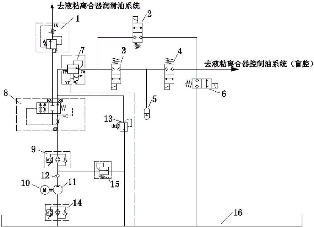
[0016] like figure 1 As shown, the present invention includes a direct-acting safety valve 15, a flow valve 1, a first two-position two-way switch valve 2, a second two-position two-way switch valve 3, a third two-position two-way switch valve 4, and a fourth two-way switch valve. Position two-way switch valve 6, proportional three-way pressure reducing valve 7, flow priority valve 8, pilot relief valve 13, direct-acting safety valve 19, high pressure filter 9, oil suction filter 14, accumulator 5, motor 10. Low pressure vane pump 11, check valve 12 and oil tank 16.

[0017] like figure 1 As shown, the motor 10 drives the low-pressure vane pump 11 to work, the oil inlet of the low-pressure vane pump 11 is connected to the outlet of the oil-suction filter 14, the inlet of the oil-suction filter 14 is connected to the oil tank 16, and the oil outlet of ...


PUM


Abstract

The invention discloses a hydraulic system with a flow priority control function for small-volume blind cavity pressure control. An oil tank is connected to a low-pressure vane pump through an oil absorption filter; the low-pressure vane pump is connected to a high-pressure filter and a direct-acting safety valve respectively through a check valve; the high-pressure filter is connected to a flow priority valve; the flow priority valve is connected with a lubricating oil pipe of a hydro-viscous clutch through a flow valve; the flow priority valve is connected to a three-way proportional pressure reducing valve and a pilot overflow valve respectively; the three-way proportional pressure reducing valve, the direct-acting safety valve and the pilot overflow valve are all connected back to the oil tank; the outlet oil path of the three-way proportional pressure reducing valve is divided into two paths, one path is connected with one switch valve, and the other path is connected with two switch valves; and an energy accumulator is arranged on a pipeline. According to the hydraulic system disclosed by the invention, adjustable-flow supply for high-flow lubricating oil and constant-flow supply for low-flow control oil are realized; and meanwhile, the working point of the hydraulic system is changed through the switchover of the switch valves, and the stability of the small-volume blind cavity pressure control system is greatly improved under the condition of no influence on rapidity.

Description

technical field [0001] The invention relates to a hydraulic system, in particular to a small-volume blind cavity pressure control hydraulic system with flow priority supply for single-pump pressure control of a fluid-viscous speed-regulating clutch. Background technique [0002] As one of the key subsystems of the hydraulic clutch, the pressure control hydraulic system of the hydraulic clutch is mainly responsible for controlling the pressure of the spring cylinder of the hydraulic clutch during the operation of the hydraulic clutch, so as to control the distance between the friction plates to transmit the corresponding torque . Because the existing pressure control system only uses the pressure reducing valve to control the pressure of the chamber, under the condition of steady pressure, when the pressure of the chamber is disturbed and fluctuates, it is very easy to cause instability of the control pressure due to over-regulation, so that The speed regulation characterist...

Claims


Application Information

Patent Timeline
IPC IPC(8): F15B11/08F15B13/044F15B1/04F16D35/00
CPCF15B1/04F15B11/08F15B13/044F16D35/00
Inventor 龚国芳王飞孙辰晨廖湘平石卓杨华勇
Owner ZHEJIANG UNIV
Learn More