Shaft sleeve

A shaft sleeve and main body technology, applied in the field of shaft sleeves and mechanical parts, can solve the problems of decreased lubrication effect, deterioration of lubricating oil, accumulation, etc., and achieve the effects of reducing friction, preventing corrosion, and low manufacturing cost

Inactive Publication Date: 2016-06-22
袁静
View PDF4 Cites 0 Cited by
  • Summary
  • Abstract
  • Description
  • Claims
  • Application Information

AI Technical Summary

Problems solved by technology

Due to the continuous friction and rotation of the rotating shaft and the shaft sleeve during the matching use, high temperature will be generated during rotation, which will deteriorate the lubricating oil between the rotating shaft and the shaft sleeve,

Method used


Image

  • Shaft sleeve
  • Shaft sleeve

Examples


Embodiment Construction

[0012] The following will clearly and completely describe the technical solutions in the embodiments of the present invention with reference to the accompanying drawings in the embodiments of the present invention. Obviously, the described embodiments are only some, not all, embodiments of the present invention. Based on the embodiments of the present invention, all other embodiments obtained by persons of ordinary skill in the art without making creative efforts belong to the protection scope of the present invention.

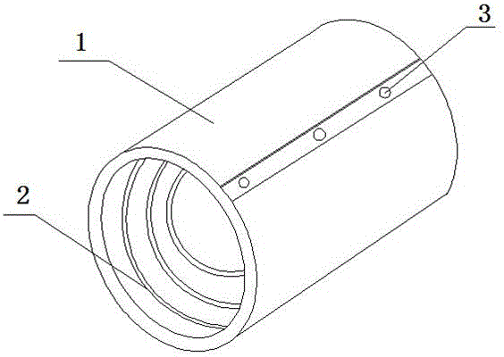
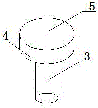
[0013] like figure 1 and figure 2 Shown: a bushing, which consists of a bushing main body 1, an oil groove 2 and an oil injection hole 3; At the other end, the oil groove 2 is rectangular, and the oil groove 2 is helically arranged on the inner surface of the shaft sleeve body 1, and the oil injection holes 3 are evenly distributed on the outer surface of the shaft sleeve body 1 with the same longitudinal extension direction. And through the side of the mai...


PUM


Abstract

The invention discloses a shaft sleeve.The shaft sleeve is characterized in that a shaft sleeve main body, an oil groove and oil injection holes are included; the oil groove is formed in the inner surface of the shaft sleeve main body and inwards extends from one end of the shaft sleeve main body to the position close to the other end of the shaft sleeve main body, the oil injection holes are evenly distributed on the same outer surface in the lengthwise extending direction of the shaft sleeve main body and penetrate through one side of the shaft sleeve main body, a gasket and a screw are arranged in each oil injection hole, and the length of the screws is smaller than the thickness of the shaft sleeve main body.The shaft sleeve has the advantages that the manufacturing technology is reasonable, the manufacturing cost is low, normal operation cannot be influenced, and the safety and reliability are achieved; air and dust can be effectively prevented from entering the shaft sleeve, friction can be reduced, rust corrosion can be prevented, and the wide market prospect is achieved.

Description

technical field [0001] The invention relates to a mechanical part, in particular to a shaft sleeve, which belongs to the field of mechanical devices. Background technique [0002] The shaft sleeve is an important part in the field of mechanical design, and the shaft sleeve is usually arranged on the rotating shaft to protect the rotating shaft. Due to the continuous friction and rotation of the rotating shaft and the shaft sleeve during the matching use, high temperature will be generated during rotation, which will deteriorate the lubricating oil between the rotating shaft and the shaft sleeve, greatly reduce the lubrication effect, and dust and debris generated by friction will also Gradually accumulated, the lack of lubrication between the shaft sleeve and the shaft, as well as the influence of thermal expansion, will eventually lead to jamming. Contents of the invention [0003] Aiming at the above-mentioned problems in the prior art, the present invention provides a ...

Claims


Application Information

Patent Timeline
IPC IPC(8): F16C33/04
CPCF16C33/04
Inventor 袁静
Owner 袁静
Why Eureka
Try Eureka