Electronic detonator controlled through detonation controller and control method thereof

An electronic detonator and controller technology, which is applied to weapon accessories, fuzes, offensive equipment, etc., can solve the problems of reducing the number of electronic detonators, reducing the reliability of electronic detonators, and slow processing speed.

Inactive Publication Date: 2016-06-22
BEIJING INSTITUTE OF TECHNOLOGYGY
View PDF5 Cites 24 Cited by
  • Summary
  • Abstract
  • Description
  • Claims
  • Application Information

AI Technical Summary

Problems solved by technology

[0004] However, the control circuit of the existing electronic detonator is generally large in size, complicated in wiring and numerous in components, which reduces the reliability of the electronic detonator to a certain extent.
The traditional electronic detonator uses RC oscillation circuit as the clock source to reduce the cost and circuit size, but this sacrifices the timing accuracy of the electronic detonator for the delay time to a certain extent
On the other hand, the low integration of existing electronic detonators also makes the processing speed of electronic detonators relatively slow for external commands, and the power consumption is high, which reduces the number of electronic detonators that can be loaded by an electronic detonator detonation controller

Method used


Image

  • Electronic detonator controlled through detonation controller and control method thereof
  • Electronic detonator controlled through detonation controller and control method thereof
  • Electronic detonator controlled through detonation controller and control method thereof

Examples


Embodiment Construction

[0064] The present invention will be further described through the embodiments below in conjunction with the accompanying drawings.

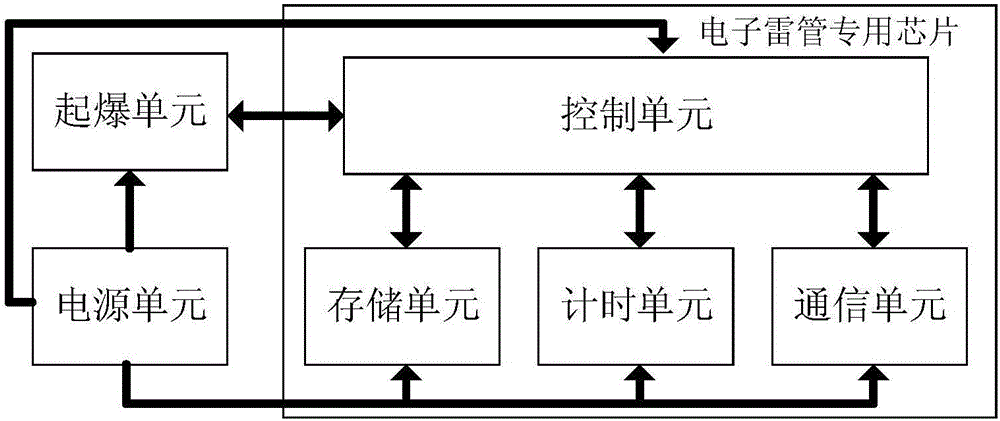
[0065] Such as figure 1 As shown, the electronic detonator controlled by the detonation controller in this embodiment includes: a power supply unit, a communication unit, a timing unit, a detonation unit, a storage unit and a control unit.

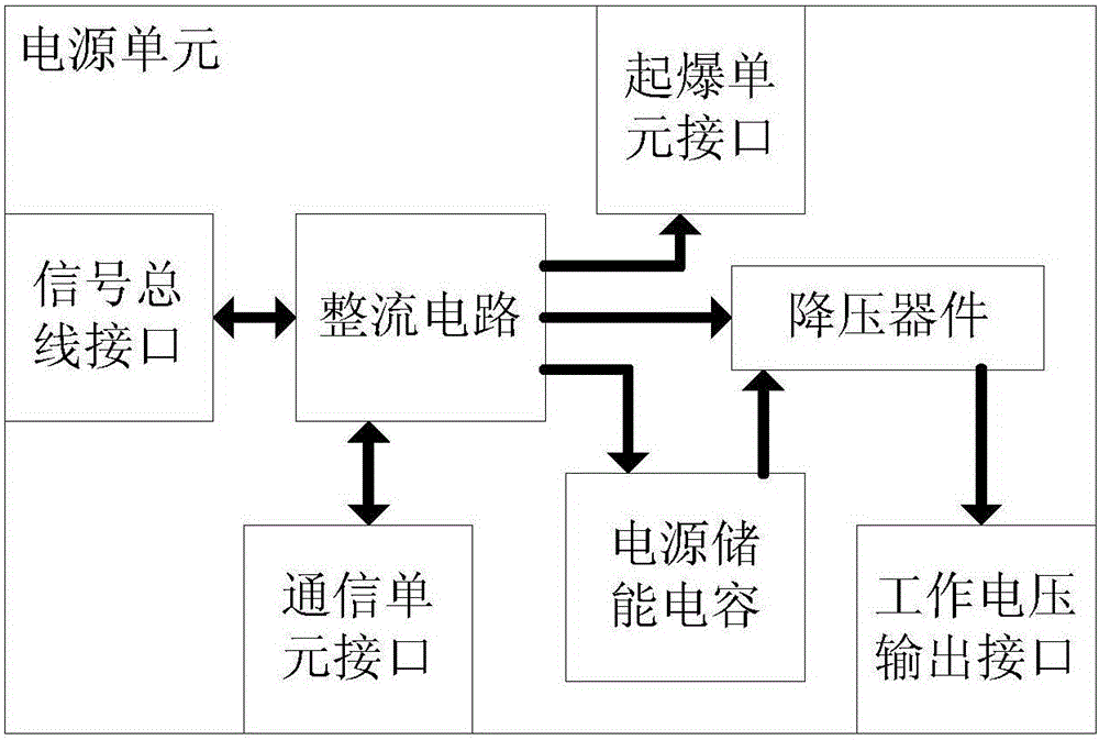
[0066] Such as figure 2 As shown, the power supply unit includes a rectifier circuit, a power storage capacitor and a step-down device; wherein, the first port of the rectifier circuit is connected to the signal bus through the signal bus interface to ensure that the voltage polarity of the signal bus input to the electronic detonator is stable, and the second port Connect to the power storage capacitor, step-down device and initiation unit interface respectively to provide input voltage for the power storage capacitor, step-down device and detonation unit; the third port is connected to the communication un...


PUM


Abstract

The invention discloses an electronic detonator controlled through a detonation controller and a control method thereof. Instructions of the control process are designed one by one, so that strict control over the detonation process is achieved. Through the four checking processes of an encoding head and an end code, a check code, a serial number and a unique code, the safety of the electronic detonator which is a dangerous initiating explosive device is improved, and hidden danger caused by misoperation is greatly reduced. By using a special chip specially designed for the electronic detonator, the size and power consumption of the electronic detonator are substantially reduced, miniaturization of the electronic detonator is achieved, and the number of electronic detonators capable of being carried on the detonation controller is greatly increased. Through the special dormancy and awakening function design, the practical power consumption of the electronic detonator in the operation process is further reduced. Through clock calibration operation and an adjustable RC oscillating circuit, microsecond level accurate reckoning of detonation delay time is achieved under the condition that low cost is guaranteed.

Description

technical field [0001] The invention relates to the detonation technology of pyrotechnics, in particular to an electronic detonator controlled by a detonation controller and a control method thereof. Background technique [0002] The existing electric detonator detonators generally use a series or series-parallel combination electric detonator network. When thousands of detonators are connected in series, in order to ensure that all the detonators in the network can detonate at the same time, the detonator detonator should be able to generate a current of one to several amperes instantaneously. There will be phenomena such as rejection of explosion and half explosion. The resistance of a single generator detonator is generally about one to several ohms, so the above-mentioned electric detonator detonator needs to have a boost circuit and be able to provide an output voltage of the order of kilovolts. Therefore, the above-mentioned electric detonator detonator has certain d...

Claims


Application Information

Patent Timeline
Patent Type & Authority Applications(China)
IPC IPC(8): F42C19/12
CPCF42C19/12
Inventor 娄文忠郭云龙卢宇飞刘鹏丁旭冉
Owner BEIJING INSTITUTE OF TECHNOLOGYGY
Why Eureka
Try Eureka