
Error modeling compensation method and system of optical remote sensing satellite image time-varying system

A time-varying system, optical remote sensing technology, applied in photogrammetry/video surveying, instrumentation, mapping and navigation, etc., can solve the problems of difficulty in identifying and compensating low-frequency error parameters, and time-varying changes in attitude reference.

Active Publication Date: 2016-06-22
WUHAN UNIV
View PDF5 Cites 13 Cited by
  • Summary
  • Abstract
  • Description
  • Claims
  • Application Information

AI Technical Summary

Problems solved by technology

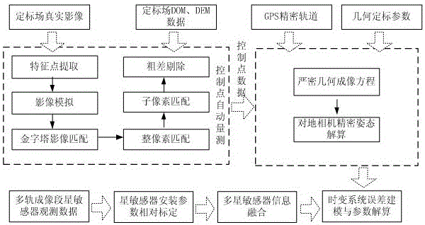
[0003] Aiming at the problems of difficult identification and compensation of low-frequency error parameters of star sensors and time-varying change of attitude reference, the present invention provides a technical scheme for modeling compensation of optical remote sensing satellite image time-varying system error

Method used


Image

  • Error modeling compensation method and system of optical remote sensing satellite image time-varying system
  • Error modeling compensation method and system of optical remote sensing satellite image time-varying system
  • Error modeling compensation method and system of optical remote sensing satellite image time-varying system

Examples


Embodiment Construction

[0037] The technical solution of the present invention will be described in detail below in conjunction with the drawings and embodiments.

[0038] see figure 1 The time-varying system error on-orbit calibration and compensation flow chart of optical remote sensing satellite image without control geometric positioning is shown, and the method of the present invention will be further described in detail for each step in the flow of the embodiment below.

[0039] Step 1. Based on the multi-satellite sensor observation data of multiple imaging time periods of the ground-to-ground camera of the optical remote sensing satellite, the relative installation parameter change sequence between star sensors is calculated, and the optimal estimated value of the installation parameter is further obtained based on the weighted average to realize star-sensing Relative calibration of the instrument installation parameters.

[0040] Assume that the quaternion observation of star sensor A at a ...


PUM


Abstract

The invention provides an error modeling compensation method and system of an optical remote sensing satellite image time-varying system. The error modeling compensation method comprises the following steps: based on observation data of a plurality of satellite sensors at a plurality of imaging time periods of a ground camera, obtained by an optical remote sensing satellite, resolving a relative mounting parameter change sequence between the satellite sensors to obtain an optimal mounting parameter estimated value; according to the observation data of the plurality of imaging time periods of the plurality of satellite sensors and the mounting parameters obtained by calibration, realizing optimal information fusion of the plurality of satellite sensors, and outputting high-precision attitude data; realizing ground camera precise attitude inversion by adopting a strict geometrical imaging model; constructing a time-varying system error compensation model by adopting Fourier series; and fusing attitude and ground camera precise attitude results according to information of the plurality of satellite sensors, and realizing optimal estimation of parameters of the time-varying system error compensation model based on a least squares principle. With the adoption of the error modeling compensation method and system, on-track compensation of low-frequency errors and non-uniform attitude standard errors of the satellite sensors can be realized, and influences on errors of a high-resolution-ratio optical remote sensing image out-of-control positioning time-varying system are effectively weakened.

Description

technical field [0001] The invention belongs to the field of ground preprocessing of remote sensing satellites, and in particular relates to a modeling compensation method and system for optical remote sensing satellite image time-varying system error modeling. Background technique [0002] The uncontrolled geometric processing of high-resolution optical satellite images is affected by a variety of error sources, among which the change of the attitude reference caused by the low-frequency error of the star sensor, the space thermal environment, and the change of the attitude reference caused by the switching of different star sensor working modes is the current Important factors affecting the precision of high-precision geometric processing of optical remote sensing images. The star sensor is a commonly used precision attitude measurement component, but due to the influence of factors such as the alternating cold and hot space thermal environment on the satellite and the cha...

Claims


Application Information

Patent Timeline
IPC IPC(8): G01C11/00G01C25/00
CPCG01C11/00G01C25/00
Inventor 王密范城城李德仁龚健雅
Owner WUHAN UNIV
Learn More